



How to Read Pressure Gauge Accuracy Ratings


A pressure gauge marked 1% accuracy does not necessarily read within 1% of the pressure currently shown on the dial. That distinction is where many specification errors begin. Knowing how to read pressure gauge accuracy means identifying the accuracy basis, applying it to the full-scale range, and confirming that the gauge is suitable for the operating pressure and process conditions.
For maintenance replacements, OEM builds, and process-control applications, gauge accuracy should be evaluated alongside wetted materials, connection size, mounting orientation, pressure range, and service conditions. A highly accurate gauge with the wrong range or an incompatible wetted material is not a reliable measurement solution.
Start With the Accuracy Statement
Most analog pressure gauges state accuracy as a percentage on the dial face, product label, or manufacturer data sheet. The percentage may be expressed as a single number, such as ±1%, or as a multi-part value, such as ±1-1.5-1%. These markings describe the maximum permissible error under defined reference conditions, not a guarantee that every reading will equal the actual process pressure.
The first question is: percentage of what? For most industrial analog gauges, the stated accuracy is a percentage of full scale. Full scale is the maximum value printed on the gauge dial. A 0-100 psi gauge has a full scale of 100 psi, while a 0-3,000 psi gauge has a full scale of 3,000 psi.
If a 0-100 psi gauge has an accuracy of ±1% of full scale, its permissible error is ±1 psi anywhere on the scale. At a displayed pressure of 50 psi, the actual pressure may be between 49 and 51 psi. At a displayed pressure of 10 psi, it may still be between 9 and 11 psi. The absolute error remains 1 psi, but the percentage of the reading becomes much larger at low pressure.
This is why a gauge should not be selected solely because its accuracy percentage looks acceptable. The expected operating point matters just as much.
How to Read Pressure Gauge Accuracy by Dial Zone
A multi-part accuracy specification divides the dial into zones. A common example is ±1-1.5-1%, which is often associated with higher-grade industrial gauges. The first value applies to the lower portion of the dial, the middle value applies through the central portion, and the final value applies near the upper end of the scale. The exact zone boundaries should always be confirmed in the manufacturer specification.
A typical interpretation is 0% to 25% of span, 25% to 75% of span, and 75% to 100% of span. On a 0-1,000 psi gauge rated ±1-1.5-1%, the allowable error may be ±10 psi in the lower and upper dial zones and ±15 psi in the middle zone.
This arrangement can seem counterintuitive because the center range has the larger tolerance. It reflects the accuracy classification method rather than a simple statement of gauge quality. Do not assume that a three-part rating is less precise than a single percentage without comparing the actual allowable error at the required operating point.
Also look for whether the gauge is specified as accuracy percent of span, percent of full scale, or percent of reading. Percent of reading is more common in digital instruments and transmitters than in conventional mechanical gauges. A ±1% of reading specification produces a smaller absolute error at lower pressures than ±1% of full scale, but it must be read exactly as stated.
Calculate the Allowable Error
The basic calculation for a full-scale accuracy rating is straightforward:
Allowable error = Full-scale pressure range × accuracy percentage
For a 0-600 psi gauge rated at ±2% of full scale:
600 psi × 0.02 = ±12 psi
If the gauge indicates 300 psi, the actual process pressure may be between 288 and 312 psi under the applicable reference conditions. If the same gauge indicates 60 psi, the actual pressure may be between 48 and 72 psi. The gauge may still meet its published accuracy specification, but it may not provide enough useful resolution for a 60 psi operating point.
For a compound gauge, calculate accuracy from the entire span, not only the positive-pressure side. A gauge scaled from -30 inHg to 100 psi has a combined span that must be evaluated according to the manufacturer’s stated accuracy convention. Vacuum and compound service deserve particular attention because dial graduations, unit conversion, and the reference pressure can complicate interpretation.
Select a Range That Keeps Normal Pressure in the Useful Dial Area
Gauge range selection directly affects practical accuracy and readability. For stable operating pressure, a common selection approach is to choose a gauge whose normal pressure falls near the middle portion of the dial. This provides a readable indication, limits the relative effect of full-scale error, and leaves room for expected pressure changes.
For systems with pulsation, cycling pressure, or occasional surges, the selected range may need additional headroom. A gauge operating continuously near its maximum scale can experience increased mechanical stress and may not provide adequate margin for upset conditions. On the other hand, selecting an excessively high range makes low-pressure readings difficult to interpret accurately.
Consider a process that normally runs at 90 psi. A 0-100 psi gauge may place normal operation near the high end of the dial, leaving little surge capacity. A 0-160 psi gauge may be a better fit if pressure is stable and expected excursions are modest. If the system experiences frequent pulsation or higher pressure spikes, a 0-200 psi or higher range may be appropriate, provided the resulting allowable error still meets the process requirement.
The best range depends on the actual operating envelope, not a universal percentage rule. Review normal pressure, maximum operating pressure, possible overpressure, and the minimum change in pressure that personnel or controls must detect.
Understand Accuracy Grade and Application Requirements
Accuracy grades provide a useful comparison point, especially when a specification references ASME B40.100 or another governing standard. Lower numerical accuracy values indicate tighter permissible error. A gauge rated 0.5% accuracy is generally more precise than one rated 1% or 2% accuracy, assuming the ratings use the same basis.
Higher-accuracy gauges are appropriate when pressure readings support quality control, equipment testing, calibration checks, or closely controlled process conditions. Standard commercial or general industrial gauges may be sufficient for noncritical utility pressure, basic equipment monitoring, or applications where a broad pressure change matters more than an exact value.
Do not pay for a tighter accuracy class if other factors dominate the uncertainty. A gauge connected through a plugged impulse line, exposed to severe vibration, or installed where temperature varies significantly may not deliver meaningful field accuracy even if its published dial specification is excellent.
Account for Installation and Service Conditions
Published gauge accuracy is typically established under controlled conditions. Actual performance can be affected by ambient temperature, process temperature, vibration, pulsation, shock, mounting stress, and contamination. Mechanical gauges can also shift over time due to wear, overpressure events, or repeated cycling.
Pressure snubbers, restrictors, gauge protectors, diaphragm seals, and proper mounting can improve service life and stabilize readings in demanding applications. However, each added component can introduce response lag or other system effects. A diaphragm seal is often necessary for corrosive, viscous, sanitary, high-temperature, or solids-laden media, but the assembly should be selected and filled correctly for the temperature and pressure conditions involved.
Before installing a replacement gauge, verify the process connection, thread standard, wetted materials, case style, dial size, mounting configuration, and pressure range. A 1/4 inch NPT lower-mount gauge and a 1/4 inch NPT back-mount gauge may share a pressure range yet serve very different panel or piping arrangements.
Verify Accuracy Through Calibration and Inspection
A gauge should be checked against a traceable reference when the measurement affects safety, product quality, billing, compliance, or critical maintenance decisions. During a calibration check, compare the gauge indication at multiple increasing and decreasing pressure points. This identifies not only error, but also hysteresis, pointer friction, and poor return to zero.
A gauge that does not return to zero after pressure is removed should be investigated before it is relied upon. The cause may be mechanical damage, a prior overpressure event, blocked sensing passages, or normal wear. Visible case damage, a cracked window, corrosion, or a bent pointer are also reasons to remove the instrument from critical service.
For specification-driven replacement and new-system work, document the required accuracy at the actual operating pressure, then select the gauge range and accuracy class accordingly. Mass Measure supports industrial buyers who need to match those requirements to specific NOSHOK gauge series, connections, materials, and service conditions.
A pressure gauge is most useful when its stated tolerance is translated into an actual number of psi, bar, or other process units at the point where the system operates. Make that calculation before purchasing, then treat calibration, installation, and process compatibility as part of the measurement requirement rather than afterthoughts.
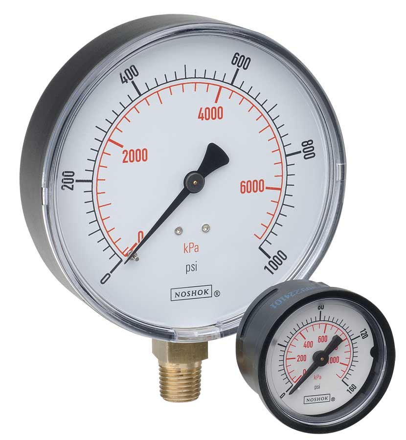 NOSHOK ABS & Steel Dry Pressure Gauges 100 series
 NOSHOK Low Pressure Dry Pressure Gauges-( 200 series)
 NOSHOK PT40 Series High Accuracy Transmitters-Replaces 100,200,615 series