



Pressure Transmitter Crossover Example Explained


A pressure transmitter crossover example is most useful when a replacement appears to match on the surface but may differ in a specification that affects installation, measurement accuracy, or plant approval. A 0-100 psi transmitter with a 4-20 mA output is not automatically interchangeable with another 0-100 psi, 4-20 mA unit. The process connection, wetted material, electrical entry, pressure reference, environmental rating, and required certifications still need to align.
For maintenance teams and procurement buyers, a crossover should be treated as a controlled comparison. It identifies a potential replacement path, then confirms whether the proposed transmitter will perform the same job within the existing process, control system, and installation constraints.
What a Pressure Transmitter Crossover Must Match
A correct crossover begins with the installed transmitter’s complete manufacturer part number. The model number often defines more than the measuring range. It can encode sensor technology, housing material, process thread, electrical connector, output protocol, accuracy class, approvals, and options such as display or remote seal capability.
Start with the application requirement rather than the product description alone. “Pressure transmitter, 100 psi, 4-20 mA” is a useful search description, but it is not a complete specification. A transmitter installed on a hydraulic power unit has different material, overpressure, and vibration considerations than one used on a sanitary washdown skid or a chemical injection line.
The replacement should be evaluated in three categories: process fit, electrical and control-system fit, and environmental or compliance fit. A mismatch in any one category can turn an otherwise close alternate into an unsuitable replacement.
Process fit
The pressure range must cover normal operating pressure while providing useful measurement resolution. The range should not be selected solely because it equals the old transmitter’s label. If process conditions have changed, an engineering review may show that a different calibrated span is appropriate.
Confirm the pressure reference as well. Gauge pressure, absolute pressure, vacuum-capable measurement, and compound ranges are not interchangeable. A gauge transmitter referenced to atmosphere cannot replace an absolute transmitter in a vacuum process simply because both show similar numerical values at one operating point.
Then verify the process connection and wetted materials. Thread type and size must match the mating port, including NPT, SAE, or other connection standards. The wetted diaphragm, port, and seal materials must withstand the media, temperature, cleaning chemicals, and corrosion exposure. For demanding media, a nominally similar stainless steel construction may still be insufficient if the original application required a specialized diaphragm material or a diaphragm seal assembly.
Electrical and control-system fit
Most industrial pressure transmitter replacements involve a 4-20 mA loop, but output format alone does not establish compatibility. Check whether the transmitter is a two-wire loop-powered device or requires separate power. Confirm supply voltage, maximum loop resistance, polarity requirements, and the input card’s expected signal type.
If the installed device communicates through HART or another protocol, determine whether that capability is required for commissioning, field configuration, diagnostics, or asset management. A basic analog unit may operate in the loop but remove functions the plant relies on.
Electrical termination also matters. An M12 connector, DIN connector, conduit connection, and integral cable each affect installation labor and enclosure integrity. Verify pinout where applicable. Do not assume that matching connector styles have matching terminal assignments.
Environmental and compliance fit
The housing and ingress rating need to suit the location. Indoor panel applications, outdoor pump stations, washdown areas, and exposed process units create different requirements for moisture, dust, vibration, UV exposure, and temperature cycling.
Hazardous-location approvals require particular care. A transmitter listed for one classification, wiring method, or protection concept is not necessarily approved for another. Confirm the required area classification against the transmitter’s exact approval marking and installation documentation. Approval status should never be inferred from a similar model family.
Pressure Transmitter Crossover Example: A Practical Review
Consider an existing transmitter installed on a water booster skid. The nameplate indicates a 0-150 psi gauge range, 4-20 mA two-wire output, 1/4 inch NPT male process connection, 316 stainless steel wetted components, and a DIN electrical connector. The transmitter is mounted near the discharge header and feeds a PLC analog input for pump staging.
A proposed crossover has the same 0-150 psi range and 4-20 mA output. Those matches are necessary, but the review should continue.
First, compare the process port. If the proposed transmitter has a 1/4 inch NPT male connection, it may mount directly. If it has a different thread standard or a larger port, an adapter may be possible, but the adapter introduces additional leak paths, may alter mechanical clearance, and can complicate maintenance. Direct connection is generally preferable when the original installation was designed around a specific fitting geometry.
Next, compare wetted materials. A 316 stainless steel sensor port and diaphragm are generally appropriate for many water service applications, but the actual water chemistry matters. Chloride exposure, added treatment chemicals, and high operating temperature may require a more specific materials review. The housing material is separate from the wetted material and should be checked independently.
Then verify the electrical loop. The replacement’s supply-voltage requirement and allowable load must support the installed PLC input, cable run, and 24 VDC power supply. If the old unit used a DIN connector with a specific terminal arrangement, the field wiring must be verified against the replacement wiring diagram before energizing. Reusing an existing connector without checking pinout can create a no-signal condition or damage equipment.
Finally, review accuracy and overload capability. A 0.5% accuracy transmitter may be suitable where the original control scheme only needs reliable pump staging. It may not be adequate where the signal supports custody, quality, or narrow process-control limits. Similarly, the transmitter’s proof pressure and burst pressure must tolerate expected pressure spikes from pump starts, valve closure, or water hammer.
In this example, the crossover is acceptable only after the physical, electrical, and performance requirements are confirmed. The identical range and output made it a candidate. They did not make it an approved replacement by themselves.
How to Build a Reliable Crossover Record
For recurring maintenance requirements, document the installed device and approved alternate in a format that purchasing, maintenance, and engineering can use consistently. Record the full legacy part number, approved replacement part number, calibrated range, process connection, wetted materials, output, electrical connection, accuracy, pressure limits, temperature limits, and required approvals.
Also record application-specific exceptions. For example, a transmitter may be acceptable for general utility water service but not for a chemical dosing skid, even when the nominal pressure range is identical. This distinction prevents a broadly described stock item from being installed in the wrong service.
A formal crossover record is especially valuable when original equipment is obsolete, lead times are extended, or multiple facilities maintain similar equipment. It supports faster purchasing without bypassing technical control. It also gives storeroom teams a clearer basis for stocking spare transmitters by approved configuration rather than by vague descriptions.
Common Crossover Errors to Avoid
The most frequent error is crossing by pressure range and output only. Other common problems include selecting gauge pressure instead of absolute pressure, overlooking a different process thread, assuming stainless steel always means identical corrosion resistance, and ignoring electrical connector differences.
Another issue is replacing a transmitter with a unit that has a different zero and span configuration method. A device may be mechanically and electrically compatible but require field adjustment tools or procedures that are not available to the maintenance team. If the application depends on a local display, diagnostic indication, or a specific communication protocol, those features should be listed as requirements rather than treated as optional conveniences.
For NOSHOK PT Series configurations, use the complete part number and application data to identify the appropriate crossover path. Mass Measure can help industrial buyers work from exact series, connection, range, and material requirements instead of relying on a partial description.
The right replacement is the one that preserves the measurement function and installation requirements already engineered into the process. When the nameplate data is incomplete, verify the transmitter against the process conditions and control documentation before releasing a crossover for purchase or installation.
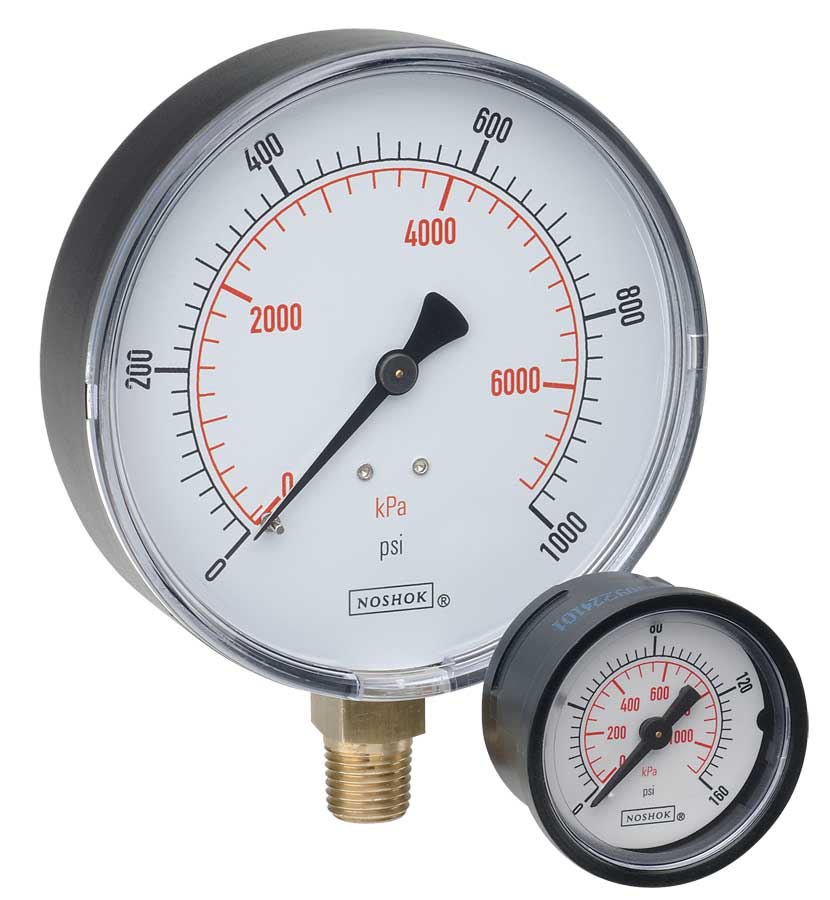 NOSHOK ABS & Steel Dry Pressure Gauges 100 series
 NOSHOK Low Pressure Dry Pressure Gauges-( 200 series)
 NOSHOK PT40 Series High Accuracy Transmitters-Replaces 100,200,615 series