



How to Size Diaphragm Seals for Process Duty


A diaphragm seal is often selected after a pressure gauge or transmitter has already been specified. That sequence can create problems. A seal that fits the process nozzle but is mismatched to the instrument range, process temperature, or fill system can introduce response lag, temperature error, or premature failure. Knowing how to size diaphragm seals means sizing the complete pressure measurement assembly, not only the threaded or flanged process connection.
For maintenance replacements, begin with the existing instrument and seal part numbers, process connection, wetted material, fill fluid, and capillary length. For new installations, define the process conditions before choosing a seal configuration. Exact documentation matters because two assemblies with the same nominal pressure rating can perform very differently in service.
How to size diaphragm seals as a complete system
A diaphragm seal isolates the sensing element from the process with a flexible diaphragm and a filled pressure-transfer cavity. Process pressure deflects the diaphragm and transfers force through the fill fluid to the gauge, switch, or transmitter. Every part of that system affects the result.
Start by identifying the instrument type and its calibrated range. The diaphragm seal must be compatible with the instrument connection, but connection fit alone is not sufficient. The instrument range must accommodate normal operating pressure, expected surges, and the pressure error contributed by the seal system.
A low-range instrument paired with a large-volume seal, long capillary, or high-temperature process may be less accurate than the same instrument mounted directly to the process. Conversely, a higher-range instrument may tolerate system effects but provide inadequate resolution for the operating point. Select the range around the actual control, monitoring, or alarm requirement rather than simply using the maximum line pressure.
Define normal, maximum, and transient pressure
Record normal operating pressure, maximum continuous pressure, proof or overpressure exposure, and any pressure spikes. Pump discharge, compressor pulsation, valve closure, thermal expansion, and blocked-in liquid can all produce short-duration pressures that exceed normal process values.
The diaphragm, body, welds, flange, and instrument must each have suitable pressure capability. Do not treat the seal pressure rating as permission to exceed the gauge or transmitter rating. The lowest-rated component establishes the allowable assembly limit.
Vacuum service requires separate attention. Some diaphragm constructions and fill fluids are more appropriate for vacuum or compound-pressure applications than others. A system intended to measure slight positive pressure may not maintain acceptable performance when exposed to full vacuum, especially at elevated temperature or with a large fill volume.
Select the process connection and diaphragm geometry
The process connection determines how the seal sees the process, how readily it can be cleaned, and whether the diaphragm is protected or exposed. Threaded seals are common for general industrial pressure service, while flanged, flush-mounted, sanitary, and specialized configurations address applications with plugging, corrosion, hygiene requirements, or high viscosity.
Connection selection should account for the process nozzle standard, thread type or flange class, available mounting space, and need for removal. A nominally compatible connection can still be unsuitable if the diaphragm is recessed into a dead zone where solids accumulate or if the installation does not provide adequate clearance for a flange or clamp connection.
Diaphragm diameter and shape also matter. Larger diaphragms can improve sensitivity and are often useful for lower pressure ranges, but they may increase displacement volume and temperature-related effects. Smaller diaphragms may suit higher-pressure service and confined installation spaces. The correct choice depends on the required measurement range, process medium, and the manufacturer-approved operating limits for the specific seal series.
For viscous, crystallizing, polymerizing, or slurry service, prioritize a flush diaphragm arrangement that minimizes pockets between the process and sensing surface. A standard threaded seal with a narrow pressure port can become plugged even when its materials are chemically compatible. In sanitary service, select a configuration that matches the required hygienic connection and cleaning method, not just the pressure range.
Match wetted materials to the process
Wetted material selection is a chemical and mechanical decision. The diaphragm is usually the most critical wetted component because it is thin and directly exposed to the process. The body, flange, gasket contact surfaces, and any wetted fasteners must also be considered.
Stainless steel is widely used, but it is not automatically appropriate for chloride-bearing fluids, strong acids, sour service, high-temperature caustics, or other aggressive media. More corrosion-resistant alloys, fluoropolymer-lined designs, and application-specific diaphragm materials may be required. Material compatibility should be verified against the actual concentration, temperature, contaminants, and cleaning chemicals, not only the primary process description.
Abrasion is another sizing factor. A slurry may be chemically mild yet erode a thin diaphragm over time. In these applications, seal orientation, process velocity, diaphragm profile, and the ability to isolate the instrument for inspection can be as relevant as alloy selection.
Account for temperature, fill fluid, and capillary length
Temperature is one of the most common causes of diaphragm seal measurement error. As process temperature changes, the fill fluid expands or contracts. The diaphragm, seal body, capillary, and instrument sensing element also respond to temperature. These effects can shift the indicated pressure, particularly on low-range gauges and transmitters.
Specify the minimum and maximum process temperature, the expected ambient temperature around the instrument, and whether either condition cycles. A steady high-temperature application may need a cooling element, extended neck, remote-mounted instrument, or a capillary system. Each option involves trade-offs. Moving the instrument away from heat can improve instrument life, but added capillary length and fill volume can reduce response speed and increase temperature effects.
Fill fluid must be compatible with the operating temperature range and the application requirements. If a diaphragm fails, the fill fluid can enter the process, so food, pharmaceutical, oxygen, environmental, and sensitive chemical applications may impose additional restrictions. Low-temperature service can require a fluid with acceptable viscosity and freezing characteristics, while high-temperature service requires adequate thermal stability.
Keep capillaries as short as installation conditions allow. Long capillary runs are sometimes necessary for access, vibration isolation, or heat separation, but they should not be treated as a routine convenience. Longer runs add internal volume, delay pressure transmission, and create more opportunity for thermal gradients. Route capillaries away from extreme heat sources, protect them from crushing, and maintain the bend radius specified for the assembly.
Check instrument compatibility and expected performance
Sizing is complete only when the seal system and pressure instrument are reviewed together. Confirm the instrument connection type, mounting orientation, allowable temperature at the sensing element, and calibrated range. For transmitters, confirm that the assembly is suitable for the required accuracy, turn-down, response time, and output stability.
Gauge applications need the same discipline. A diaphragm seal can protect a mechanical gauge from corrosive or plugging media, but the assembly may react differently to pulsation, rapid cycling, or temperature swings than a direct-mounted gauge. If vibration or pulsation is present, address it with the correct instrument construction and system design rather than assuming the diaphragm seal will solve the problem.
The seal system’s displacement volume must also be appropriate for the instrument sensing element. As the diaphragm deflects under pressure, fluid movement is transferred to the instrument. A mismatch can affect zero shift, span, response, and overload behavior. Manufacturer assembly data is the appropriate source for confirming these limits, especially for low differential pressures, long capillaries, elevated temperatures, and demanding accuracy requirements.
Document the application before ordering
A complete specification avoids replacement delays and reduces the chance of receiving an assembly that is mechanically correct but unsuitable for the service. Include the instrument model and range; process medium; normal, maximum, and vacuum pressure; process and ambient temperatures; process connection; required wetted materials; fill fluid restrictions; capillary length; and any sanitary, hazardous-area, or cleaning requirements.
For an existing installation, photograph the nameplate and record the complete part number before removing the assembly. Do not assume a replacement diaphragm seal can be selected by thread size alone. Fill fluid, diaphragm material, instrument connection, and calibration can be integral to the original configuration.
When the process is difficult, involve the instrument supplier before installation rather than after a reading becomes unstable. A properly specified diaphragm seal assembly protects the pressure instrument while preserving the measurement the process depends on.
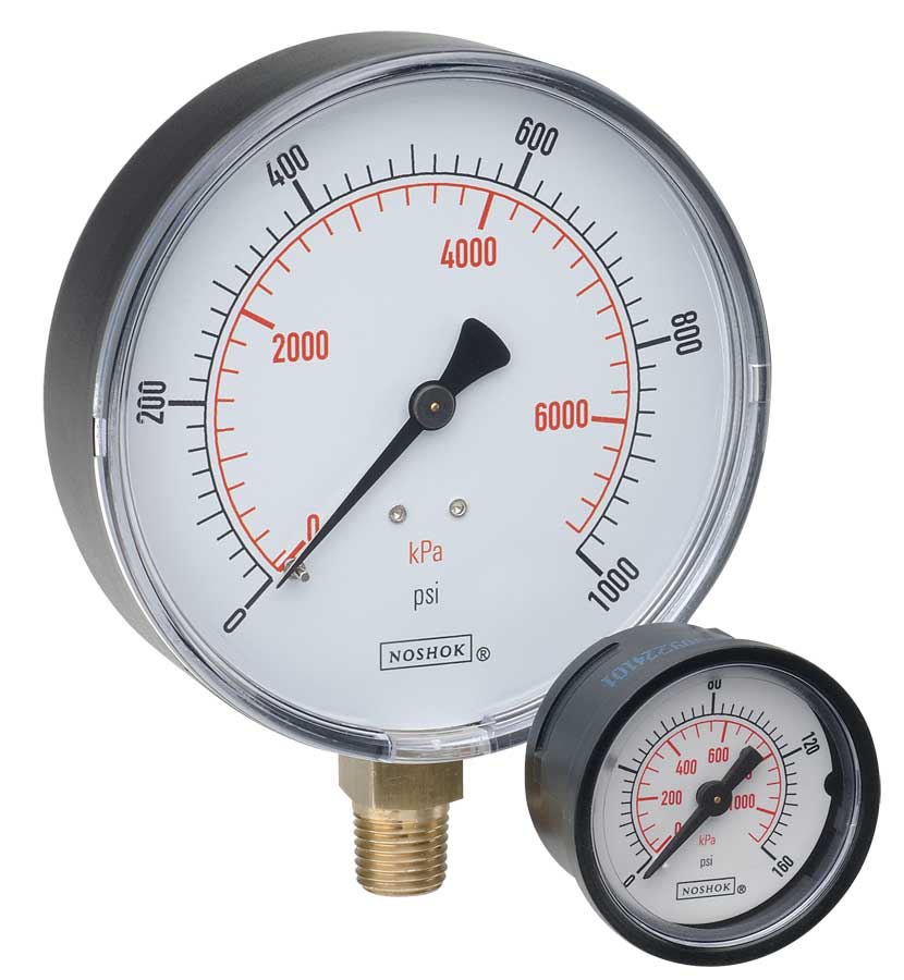 NOSHOK ABS & Steel Dry Pressure Gauges 100 series
 NOSHOK Low Pressure Dry Pressure Gauges-( 200 series)
 NOSHOK PT40 Series High Accuracy Transmitters-Replaces 100,200,615 series