



Selecting Instrumentation Fittings and Adapters

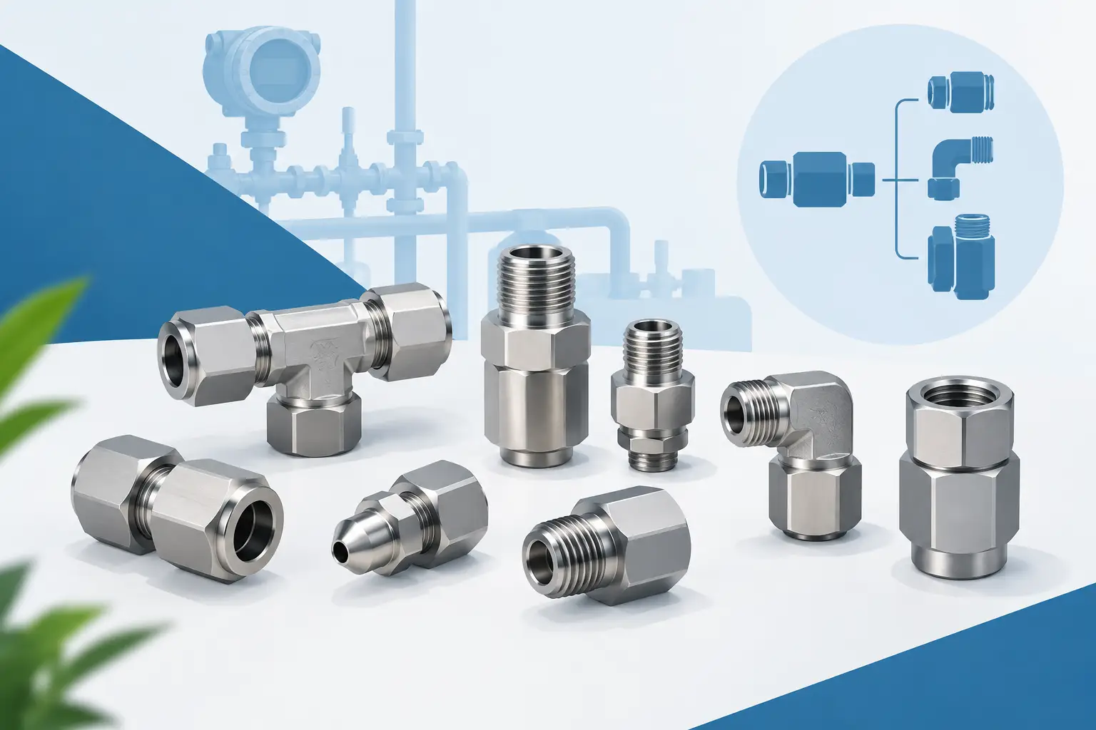
A pressure gauge can be correctly specified and still deliver unreliable information if the connection hardware is wrong. Instrumentation fittings and adapters establish the mechanical and pressure boundary between the process, impulse line, valve manifold, transmitter, or gauge. Their selection affects leak integrity, maintainability, material compatibility, and the quality of the measurement reaching the operator or control system.
For maintenance replacement, the fitting may appear to be a simple item: match the thread and install it. In process instrumentation, that approach can create repeated leaks, damaged ports, restricted flow paths, or an installation that cannot be safely serviced. The correct component must match the connection standard, thread form, material, pressure and temperature limits, media, and available installation space.
What Instrumentation Fittings and Adapters Do
Instrumentation fittings join components that are already designed to perform a measurement or control function. Common examples include adapting a gauge process port to plant piping, connecting tubing to a transmitter manifold, changing from male to female threaded connections, or joining dissimilar thread standards during a system upgrade.
An adapter changes one connection geometry to another. A fitting may provide a tubing connection, a branch connection, a union, an elbow, or a reduction. The distinction matters less than the complete connection path. Every component in that path must be suitable for the system’s maximum operating pressure, expected temperature, process media, and applicable installation practices.
In a typical pressure measurement assembly, a gauge, pressure transmitter, diaphragm seal, needle valve, manifold, and fitting package operate as one pressure boundary. The lowest-rated or least-compatible item governs the assembly. Selecting a high-pressure transmitter does not compensate for an underspecified adapter installed directly at its process port.
Start With the Connection Standard
Connection nomenclature is the first point to verify. Nominal pipe size alone is not enough. A 1/4 in. connection may refer to NPT, BSPP, BSPT, SAE straight thread, metric thread, or a tubing size, each with different sealing methods and geometry.
Tapered Pipe Threads
NPT threads seal through thread interference. They are common throughout US industrial facilities and are frequently used on pressure gauges, pressure switches, valves, and transmitters. Proper engagement and a compatible thread sealant are necessary, but over-tightening can damage female ports or split thin-wall components.
Do not assume a male NPT thread will correctly mate with every female pipe-threaded port. BSPT is also tapered but has a different thread profile and pitch. Forcing mismatched threads may feel acceptable during installation, then fail under pressure or thermal cycling.
Parallel Threads and Face Seals
BSPP, SAE, metric, and other straight-thread connections generally do not seal on the threads alone. Their sealing method may use an O-ring, bonded seal, gasket, cone seat, or machined face. If the required seal is missing, a correctly threaded adapter can still leak immediately.
This is especially relevant when replacing imported equipment or connecting an OEM skid to plant-standard instrumentation. Confirm both the thread designation and the intended sealing interface before ordering an adapter.
Tube Fittings
Tube fittings create a mechanical and pressure-tight connection to instrument tubing. Tubing outside diameter, wall thickness, material, hardness, and installation procedure all influence performance. A 3/8 in. tube fitting is not interchangeable with a 3/8 in. NPT connection without the appropriate transition fitting.
For vibration-prone service, high-pressure impulse lines, and hazardous media, tubing support and routing are as important as fitting selection. A properly specified fitting cannot correct for unsupported tubing that transmits continual stress into a transmitter or valve body.
Match Material to Media and Environment
Material selection should account for the process fluid, cleaning chemicals, ambient atmosphere, temperature, and potential galvanic interaction between joined metals. Brass may be suitable for many clean air, water, and compatible hydraulic applications. Stainless steel is often selected for corrosive environments, outdoor installations, chemical service, and applications requiring improved durability.
However, stainless steel is not a universal answer. Chloride exposure, specific acids, high temperatures, and sanitary chemicals may require a more detailed compatibility review. In sanitary or food processing applications, surface condition, cleanability, and the seal material can matter as much as the fitting body alloy.
Sealants and elastomers deserve the same review. PTFE-based thread sealants have broad chemical resistance, but they are not appropriate for every assembly method or every oxygen-related application. O-rings and gaskets may be exposed to chemicals that the metal body tolerates well. The compatibility assessment must cover the complete wetted path.
Verify Pressure and Temperature Ratings as an Assembly
Pressure ratings are not interchangeable across fitting styles, sizes, and materials. A reducer, elbow, tubing connection, or threaded adapter can carry a different rating than a straight fitting of the same nominal size. Ratings may also decrease as temperature rises.
Use the maximum operating pressure, not the normal process pressure, for selection. Consider pressure spikes, pump pulsation, compressor cycling, thermal expansion in blocked lines, and the proof or test pressure used during commissioning. A fitting that operates near its limit during routine service leaves little margin for these conditions.
Where a gauge or transmitter is installed on pulsating pressure, the fitting arrangement should also support measurement stability. Restrictors, snubbers, or dampening devices may be needed, but they must be selected carefully. Excessive restriction can slow instrument response and make a rapidly changing process appear stable when it is not.
Choose Geometry for Access and Serviceability
The shortest connection is not always the best installation. A close nipple or straight adapter may place a gauge against a hot pipe, prevent access to a calibration port, or leave no room to apply a wrench without loading the instrument case. Elbows, swivel arrangements, and properly located isolation valves can improve readability and make replacement safer.
Orientation matters for certain instruments. A pressure transmitter mounted on a vapor line may require a different impulse-line arrangement than one installed on a liquid line. Differential pressure installations require consistent high- and low-side routing. The fittings should support the intended installation geometry rather than force a compromise after the instrument arrives.
Avoid building long stacks of adapters simply to bridge an unknown connection mismatch. Each additional joint adds a potential leak point, increases unsupported weight, and can create a difficult-to-service assembly. If a transition is permanent and repeated across equipment, a purpose-selected fitting or revised connection design is usually preferable.
A Practical Selection Sequence
Before selecting instrumentation fittings and adapters, document the existing process connection and the connection required by the instrument or accessory. Record the thread type, gender, nominal size, sealing method, material, pressure range, temperature range, and media. If the existing part is available, capture its full manufacturer marking and verify it against the equipment documentation.
Next, define whether the component is intended for direct process mounting, impulse-line service, tubing transition, venting, draining, or calibration access. This prevents a common purchasing error: ordering a fitting that technically connects but does not provide the necessary function or orientation.
Then review installation constraints. Confirm wrench clearance, instrument position, vibration exposure, line loading, and whether the connection must be disconnected during preventive maintenance. For transmitter assemblies, verify the manifold and process adapter arrangement as a group. For gauges, confirm that the fitting does not defeat the intended use of a gauge valve, siphon, snubber, or diaphragm seal.
Mass Measure supports spec-driven buyers with instrumentation-grade components and NOSHOK product knowledge, which is useful when a replacement must match an established gauge, transmitter, valve, or manifold configuration rather than merely approximate it.
Common Mistakes That Create Field Problems
The most frequent mistake is treating thread size as a complete specification. A 1/2 in. designation does not identify the thread family, pitch, gender, or seal arrangement. The second is using incompatible materials because the fitting is only viewed as a temporary connector. Temporary installations often remain in service for years.
Another concern is excessive thread sealant. Applying sealant too close to the first thread can introduce debris into small instrument passages, restrict ports, or interfere with pressure measurement. Use the sealant specified for the service and apply it in a controlled manner that keeps material out of the process path.
Finally, do not use the instrument housing as a wrenching surface to tighten the fitting. Apply torque to the designated hex or wrench flats, support the assembly where necessary, and follow the manufacturer’s installation guidance. This helps prevent distorted ports, damaged sensing elements, and stress transferred into tubing or manifold connections.
A fitting is a small line item in an instrumentation bill of materials, but it determines whether the rest of the assembly can perform as specified. When the connection standard, seal method, materials, ratings, and installation geometry are confirmed before purchase, the result is a measurement point that is easier to commission, easier to maintain, and more dependable in service.
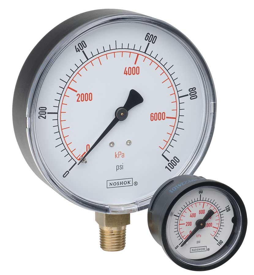 NOSHOK ABS & Steel Dry Pressure Gauges 100 series
 NOSHOK Low Pressure Dry Pressure Gauges-( 200 series)
 NOSHOK PT40 Series High Accuracy Transmitters-Replaces 100,200,615 series