



Block and Bleed Manifold Comparison Guide

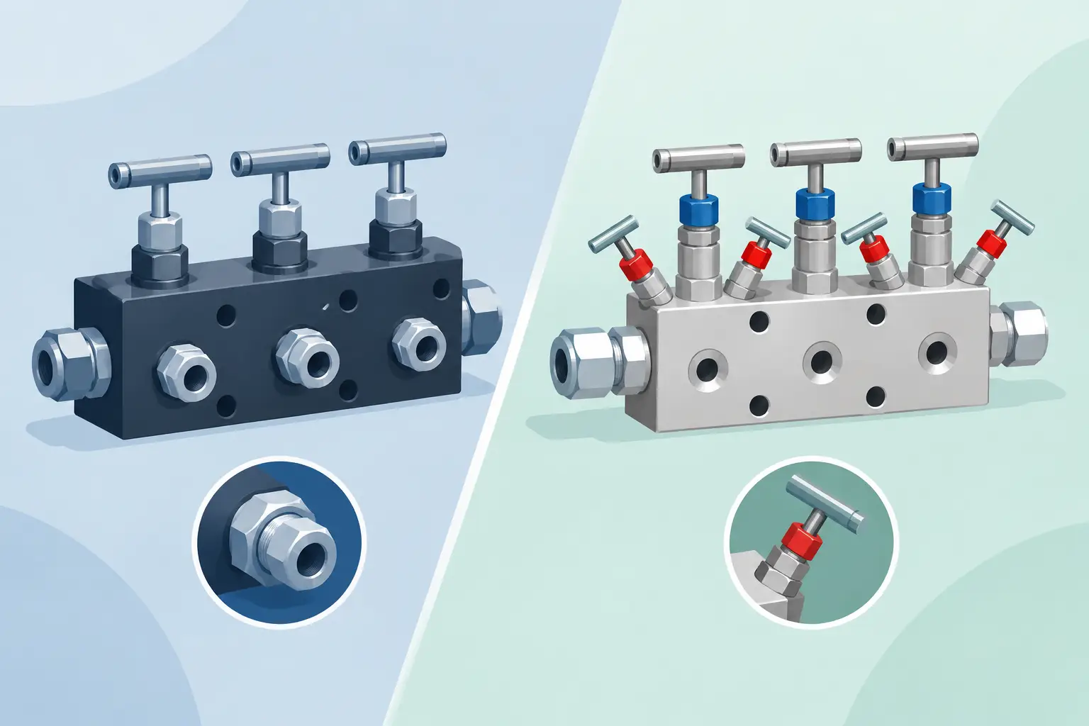
A block and bleed manifold comparison starts with one operating question: does the instrument need only to be isolated and vented, or must it also be equalized for differential-pressure measurement? The answer determines whether a two-valve, three-valve, or five-valve configuration belongs at the installation. Selecting by valve count alone can lead to an instrument that is difficult to calibrate, unsafe to service, or unsuitable for the pressure measurement method.
What a Block and Bleed Manifold Does
A block and bleed manifold combines process isolation and controlled venting in a compact valve assembly. The block valve closes the connection between the process and the instrument. The bleed valve then provides a controlled path to vent trapped pressure from the instrument side of the isolation valve.
This arrangement allows technicians to remove, inspect, replace, or calibrate a pressure gauge, pressure switch, or transmitter without shutting down the entire process line. It also reduces the number of threaded connections compared with a separate valve and vent fitting assembly. Fewer connections can simplify installation and reduce potential leak points, provided the manifold, adapters, tubing, and sealing method are correctly specified.
The term “block and bleed” is sometimes used broadly for several manifold styles. In practical instrumentation purchasing, the valve function matters more than the label. A conventional two-valve manifold provides isolation and bleed service for a single pressure connection. Differential-pressure transmitters generally require equalization capability in addition to isolation and venting.
Block and Bleed Manifold Comparison by Configuration
Two-valve manifolds for single-pressure instruments
A two-valve manifold is the standard choice for many gauge-pressure and absolute-pressure installations. One valve serves as the block, or isolation, valve. The second serves as the bleed, vent, or test valve. With the block valve closed, pressure trapped between the process connection and the instrument can be relieved through the bleed port before maintenance begins.
This configuration is commonly used with pressure gauges, pressure transmitters, pressure switches, and other instruments connected to one process pressure source. It is compact, direct, and generally easier to specify than a differential-pressure manifold. The critical selection details are pressure rating, wetted material, inlet and outlet connection types, vent-port arrangement, and temperature compatibility.
A two-valve manifold is not an interchangeable substitute for a differential-pressure transmitter manifold. It can isolate one pressure path, but it cannot equalize high-side and low-side pressure across a differential-pressure sensing element.
Three-valve manifolds for differential-pressure service
A three-valve manifold typically includes two isolation valves and one equalizing valve. Each isolation valve controls either the high-pressure or low-pressure process connection. The equalizing valve connects the two sides of the transmitter so pressure can be balanced across the sensing element.
This design is appropriate where a differential-pressure transmitter requires isolation from both process taps and equalization during startup, shutdown, or calibration procedures. However, a standard three-valve configuration may not provide individual bleed valves for venting or draining each side. Whether that is acceptable depends on the transmitter procedure, process medium, and site maintenance practice.
For clean gas service or installations where a separate venting arrangement is already provided, a three-valve manifold may be sufficient. For liquid service, corrosive media, hazardous fluids, or applications that require controlled depressurization of both impulse lines, a five-valve manifold is often more appropriate.
Five-valve manifolds for isolation, equalization, and venting
A five-valve manifold adds two bleed or vent valves to the functions provided by a three-valve unit. It includes two block valves, one equalizing valve, and a bleed valve on each pressure side. This provides greater control when removing a differential-pressure transmitter from service, performing calibration, or relieving pressure from impulse lines.
The added valves make five-valve manifolds particularly useful in process environments where trapped pressure must be positively managed. They are often selected for flow measurement applications using differential pressure, level measurement on pressurized vessels, and other installations where the high and low sides of a transmitter must be isolated, equalized, and vented independently.
The trade-off is cost, physical size, and operating complexity. More valves also mean more procedures for technicians to follow. A five-valve manifold should be selected because its venting capability is required, not simply because it is the most feature-rich option.
Match the Manifold to the Instrument Function
The instrument type is the first filter in manifold selection. A local pressure gauge usually needs a single process isolation point and, where maintenance procedures require it, a controlled vent path. A two-valve block and bleed manifold is commonly the appropriate configuration.
A pressure transmitter measuring one line pressure follows the same basic logic. The transmitter may have a direct-mount connection, a remote connection through tubing, or an installation that includes a diaphragm seal. In each case, confirm that the manifold connection, outlet geometry, and available clearance match the instrument assembly.
Differential-pressure transmitters need a different evaluation. A transmitter used for orifice-plate flow measurement, filter monitoring, or hydrostatic level measurement has high- and low-pressure inputs. The manifold must support the required isolation and equalization sequence. If the service procedure also requires venting both sides, a five-valve design is generally the more complete arrangement.
Never assume a manifold will fit a transmitter solely because both are described as differential-pressure components. Confirm the mounting standard, bolt pattern, port spacing, thread form, and sealing interface. Coplanar-style mounting arrangements, traditional flange configurations, and pipe-mounted manifolds are not universally interchangeable.
Specification Points That Change the Correct Choice
Valve configuration is only one part of the purchase decision. Industrial buyers should review the complete pressure boundary and process compatibility requirements before matching a manifold to a part number.
Wetted material comes first. Stainless steel is common for general industrial service, but it is not automatically appropriate for every chemical, sour-gas, chloride-containing, or high-temperature process. Confirm compatibility for the valve body, stem, packing, seats, plugs, and any exposed seals. A manifold can have the correct pressure rating and still be unsuitable if its wetted materials do not tolerate the process medium.
Next, verify working pressure and temperature limits as a combined application condition. Ratings can be affected by temperature, materials of construction, packing selection, and connection design. The instrument itself, the manifold, tubing, fittings, and process connection must all be suitable for the maximum operating condition. The lowest-rated component establishes the usable system limit.
Connection details deserve the same attention. NPT thread size, female or male orientation, flange mount, tube fitting outlet, and vent-port connection all affect fit and serviceability. Thread standards must match exactly. A nominally similar connection may not provide a safe or sealable installation if its thread form differs.
Also consider the bleed destination. Venting a nonhazardous gas to a controlled local location may be acceptable under site procedures. Venting flammable, toxic, hot, corrosive, or environmentally regulated media requires a defined closed-drain, flare, recovery, or containment path. A bleed port is a controlled release point, not a permission to discharge process fluid into the work area.
Installation and Operating Considerations
A well-specified manifold can still create problems if installed without regard to orientation and access. Valve handles must remain accessible, and bleed ports must be positioned so technicians can connect a vent line or drain arrangement safely. Avoid locating vents where released liquid can contact electrical equipment, hot surfaces, walkways, or personnel.
For differential-pressure installations, impulse-line routing affects measurement stability and maintenance. Keep the high-side and low-side lines properly identified. Follow the transmitter manufacturer’s requirements for elevation, slope, condensate management, and commissioning sequence. Incorrect valve operation can expose a differential-pressure sensor to an excessive pressure differential, even when the transmitter is within its normal line-pressure rating.
Torque practices are equally important. Do not use excessive force to correct a mismatched thread or compensate for damaged sealing surfaces. Use the specified thread sealant or gasket method, follow torque guidance for mounting bolts and fittings, and pressure-test the completed assembly according to plant procedures.
Sourcing the Correct Manifold Assembly
For replacement work, start with the installed manifold’s exact configuration rather than a general description. Record the valve count, inlet and outlet connections, mounting style, body material, pressure rating, handle style, and any vent connection details. Photos of the installed orientation can help prevent ordering a physically correct part that cannot be operated once mounted.
For new designs, define the instrument function and process conditions before selecting a manifold family. NOSHOK manifold and valve options can then be matched to the required isolation, equalization, venting, material, and connection specifications. This approach is more reliable than choosing the least expensive configuration and adding adapters or external valves later.
The practical choice is straightforward: use a two-valve manifold when a single-pressure instrument needs isolation and bleed capability; use a three-valve manifold when a differential-pressure instrument needs isolation and equalization; and use a five-valve manifold when that differential-pressure installation also requires independent venting or draining. Confirm the full specification before ordering, and the manifold becomes a controlled service point rather than the weak link in an otherwise accurate measurement system.