



What Causes Transmitter Drift in Process Systems?

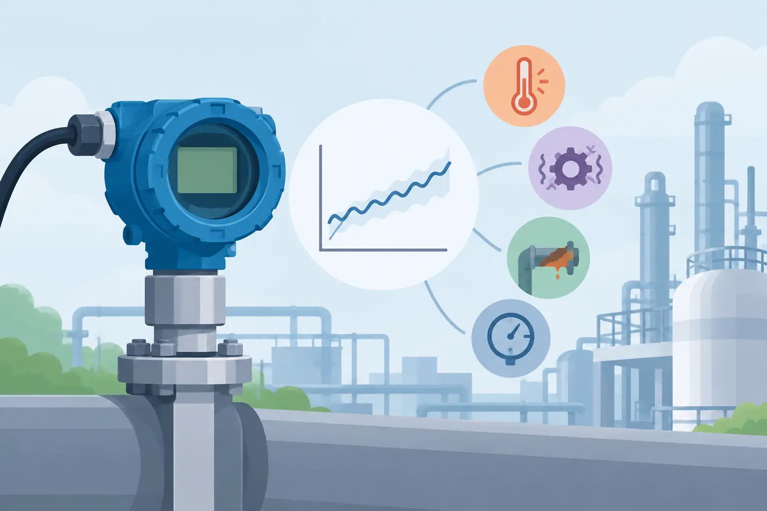
A pressure transmitter that reads 0.8% high after a shutdown may not have failed, but it has created a maintenance decision that affects product quality, control stability, and compliance. Understanding what causes transmitter drift helps teams distinguish a true change in instrument performance from a problem in the process connection, loop wiring, reference condition, or calibration method.
Drift is a gradual change in a transmitter’s output when the measured input has not changed. In practical terms, a transmitter that was calibrated to produce 4.00 mA at zero pressure and 20.00 mA at full scale may slowly begin producing a different signal for the same applied pressure. The change can occur at zero, span, or across the measurement range.
For industrial users, the relevant question is not whether any drift exists. All measurement systems have limits. The question is whether the observed change remains within the required accuracy for the application and whether it can be corrected by calibration or indicates a developing application problem.
What Causes Transmitter Drift?
Transmitter drift usually results from a combination of sensor aging, environmental exposure, process conditions, mechanical stress, and electronic changes. The construction of the transmitter matters. A thin-film, ceramic capacitive, piezoresistive, or strain-gauge sensing element can respond differently to pressure cycling, temperature variation, overpressure events, and chemical exposure.
A stable, correctly selected transmitter installed in a clean process may show only a small output shift over its calibration interval. A unit exposed to high temperature swings, pulsation, corrosive media, vibration, or repeated overloads can shift more quickly. The transmitter may still be operating, but its measurement uncertainty may no longer support the control or safety function it serves.
Sensor aging and material relaxation
The sensing element and its supporting structure are subject to small physical changes over time. Strain gauges can experience material relaxation. Bonding materials, diaphragms, fill fluids, and internal mechanical components can change slightly with long-term exposure to stress and temperature. These changes alter the relationship between applied pressure and electrical output.
This is often a gradual, predictable form of drift. It is one reason manufacturers publish long-term stability specifications, typically stated as a percentage of calibrated span over a defined time period. A transmitter selected only by pressure range and output signal may meet the initial requirement but fall short where long calibration intervals or tight process tolerances are required.
Temperature effects
Temperature is among the most common reasons for an apparent or actual output shift. Electronic components have temperature coefficients, while sensing elements and wetted diaphragms expand and contract. Even a transmitter with internal temperature compensation has specified limits for thermal zero shift and thermal span shift.
Ambient temperature affects the transmitter housing, electronics, and cable termination area. Process temperature affects the wetted diaphragm and pressure port. In steam, hot oil, furnace, compressor, and outdoor installations, the difference between a room-temperature bench calibration and operating conditions can be substantial.
A transmitter mounted directly to a hot process line may read differently after the line reaches operating temperature. That does not automatically mean the instrument is defective. The installation may require a cooling element, remote diaphragm seal, capillary system, impulse tubing arrangement, or a transmitter rated for the actual process temperature. The right approach depends on response-time requirements, process cleanliness, and the pressure range being measured.
Overpressure and pressure cycling
A pressure event above the transmitter’s rated overload capability can permanently affect the sensing element. Even when the instrument survives and continues to provide a signal, zero or span may shift. Severe events can damage diaphragms, welds, internal fill systems, or electronic circuitry.
Repeated cycling can also contribute to drift. Pumps, compressors, hydraulic systems, reciprocating equipment, and fast-acting valves create cyclic stress. Pressure spikes may be too brief to appear clearly in a control system trend, yet they can be significant enough to shorten instrument life.
A pulsation dampener, snubber, restrictor, or properly configured manifold may reduce the loading on the transmitter. These components must be selected carefully. Excessive restriction can slow response and make the indicated pressure unsuitable for a rapidly changing process.
Corrosion, plugging, and diaphragm damage
Not every changing reading is sensor drift. A blocked pressure port, accumulated solids, hardened product, damaged diaphragm, or corrosive attack can alter the pressure reaching the sensor. This is an installation and process-contact issue, but its symptoms can resemble calibration drift.
Material compatibility must cover the entire wetted path, including diaphragms, process connections, seals, O-rings, and fill fluid where applicable. Stainless steel is broadly useful but not universal. Chlorides, acids, caustics, sour service, sanitary cleaning chemicals, and abrasive slurries may require a different wetted material or a diaphragm seal arrangement.
For differential pressure applications, unequal plugging of high- and low-pressure impulse lines can create a false differential reading. Condensate legs, line routing, elevation differences, and trapped gas are equally capable of producing apparent drift. Before adjusting calibration, verify that the process pressure is reaching both sides of the measurement system as intended.
Moisture ingress and electrical issues
A transmitter may appear to drift when the actual issue is in the signal loop. Moisture in a junction box, loose terminals, damaged cable insulation, poor grounding, electrical noise, or unstable loop power can change the reported value. This is especially relevant with 4-20 mA systems routed near variable frequency drives, motors, contactors, or high-energy conductors.
Check the transmitter output directly at the instrument and compare it with the value received by the PLC, DCS, recorder, or local display. If the output at the transmitter is stable but the control-system value changes, the fault is downstream. If both values move together under a verified stable input, the transmitter or process connection deserves further investigation.
For smart transmitters, configuration must also be verified. A changed damping setting, scaled range, engineering unit selection, square-root extraction setting, or digital communication parameter can be mistaken for drift. Configuration control is particularly valuable after replacements, commissioning work, or control-system changes.
Separate True Drift From Measurement Error
Calibration should begin with a traceable pressure source appropriate for the required accuracy. Isolate the transmitter from the process, equalize and vent a differential pressure transmitter as required, and follow the applicable site procedure. Then test multiple points across the calibrated range rather than checking zero alone.
A zero-only shift may indicate installation stress, temperature effects, static pressure effects, or a modest sensor offset change. A span error may point toward sensor sensitivity changes, configuration issues, or an incorrect range setup. Nonlinearity or inconsistent results at repeated test points can indicate mechanical damage, contamination, unstable electronics, or a problem with the test equipment.
Document as-found results before making adjustments. As-found data reveals whether the transmitter is stable, drifting gradually, or changing abruptly between maintenance intervals. A record that shows repeated zero shifts after cold starts, for example, points toward thermal or installation effects rather than random sensor aging.
Selection and Installation Controls That Reduce Drift
The most effective drift control begins before installation. Select a transmitter range that places normal operating pressure in a useful portion of the calibrated span without routinely approaching the upper limit. An excessively wide range can reduce practical resolution, while an undersized range increases exposure to overload.
Match the transmitter’s accuracy, stability, turndown, wetted materials, process connection, electrical rating, and temperature limits to the service. For hazardous or washdown areas, enclosure and approval requirements also matter. A correct part number should reflect the actual process conditions, not only the connection size and output type.
Installation should protect the sensing element from avoidable heat, vibration, pulsation, freezing, and contamination. Support heavy process piping so it does not load the transmitter connection. Use suitable thread sealant without allowing material to obstruct the pressure port. Route impulse lines to avoid trapped gas in liquid service and trapped liquid in gas service.
When replacing an installed unit, verify the existing configuration instead of assuming the tag description is complete. Pressure range, output, connector type, pinout, process connection, wetted material, and approval requirements can vary within the same transmitter family. Authorized instrumentation sourcing and accurate series-level identification help prevent a replacement from introducing a new measurement problem.
Set a Calibration Interval From Evidence
A fixed annual calibration interval is common, but it is not always the most efficient approach. Critical custody, safety, batch, and quality measurements may require frequent verification. A stable transmitter in noncritical utility service may justify a longer interval if historical as-found data supports it.
Trend results by instrument type, process service, location, and failure mode. If multiple transmitters in one area show similar shifts, investigate shared environmental or process conditions. Recalibrating each unit may restore readings temporarily while leaving the root cause in place.
When a transmitter repeatedly requires a large adjustment, do not treat calibration as the repair. Inspect the process connection, confirm the reference standard, review temperature and pressure excursions, and examine whether the selected sensing technology and wetted materials fit the service. A transmitter should be expected to measure the process, not compensate indefinitely for conditions it was never specified to withstand.
The most useful maintenance record is not simply a pass or fail result. It is a record that shows how the instrument behaved in its actual service. That evidence makes the next calibration interval, replacement decision, and transmitter specification more defensible.