



Pressure Gauge Panel Mount Options

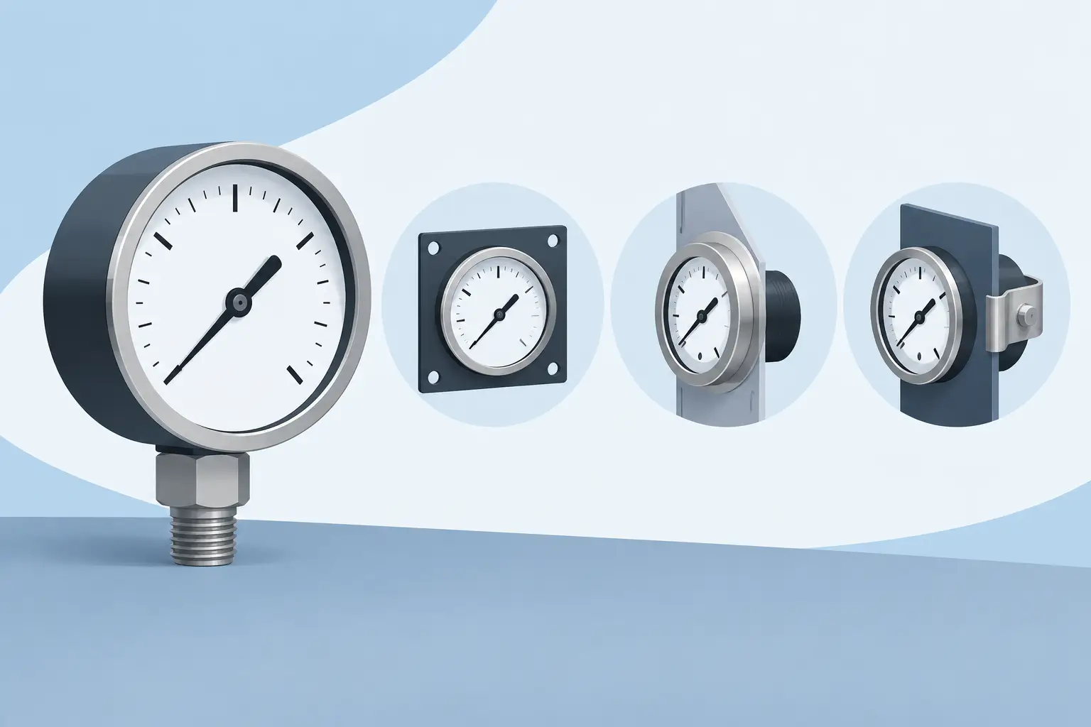
A pressure gauge mounted at an operator panel has a different job than a gauge installed directly at a process connection. The operator must be able to read it quickly, identify an abnormal condition, and trust that the indication represents the pressure at the point being monitored. Selecting among pressure gauge panel mount options therefore involves more than matching a dial size or choosing a convenient mounting hole. Case configuration, pressure connection routing, accuracy, environmental exposure, and system dynamics all affect whether the finished panel performs as intended.
For OEMs, panel builders, and maintenance teams, the best choice is usually the configuration that preserves gauge readability while keeping process connections, tubing, and service access practical behind the panel.
Pressure Gauge Panel Mount Options: Start With the Installation
A panel-mounted mechanical gauge is commonly supported by its case at the front of the panel, while the pressure connection extends behind the panel. This arrangement places the dial at eye level and moves piping or tubing away from the operating surface. It is useful for compressor skids, hydraulic power units, test stands, water-treatment equipment, and packaged process systems where several pressure points must be viewed together.
The first specification to establish is the mount style. Center back connection gauges are frequently used for panel installations because the connection exits from the rear centerline of the case. A U-clamp or equivalent rear mounting hardware can secure the gauge against the panel cutout. Front flange configurations provide a finished face around the panel opening and can improve support where the panel material is thin or vibration is a concern. A back flange configuration may also suit installations where the gauge is mounted from the rear side of the panel.
These styles are not interchangeable simply because they share the same dial diameter. The case geometry, panel cutout, connection location, and mounting hardware must be reviewed as a set. Before replacing an existing gauge, confirm whether the current instrument uses a center back connection, lower back connection, or bottom connection. A bottom connection gauge may fit a panel visually but create an awkward tubing path or require additional clearance below the panel.
Front Flange, Back Flange, and U-Clamp Mounting
A front flange mount is often selected when a clean finished panel face matters and the gauge must be retained from the front. The flange overlaps the cutout and helps conceal minor variation in the panel opening. This can be practical for OEM equipment with standardized front panels.
Back flange arrangements place the flange behind the panel face. They may be appropriate where the panel design already has a precise opening and the installation calls for rear-side fastening. The front of the gauge remains relatively flush, but access to the mounting hardware requires clearance behind the panel.
U-clamp mounting is a common, efficient choice for center back connection gauges. The clamp bears against the rear of the panel and is tightened to hold the gauge case in place. It is compact and serviceable, but the installer must leave enough room for both the clamp and the process connection. On densely packed panels, that rear clearance is often the limiting factor.
Select the Dial Size for Reading Distance, Not Just Cutout Size
Dial diameter determines more than panel appearance. It establishes how easily an operator can distinguish normal operating pressure from an alarm or relief threshold. A small dial may be acceptable on a compact machine where the operator stands within arm’s reach. A larger dial is generally more suitable for equipment monitored from several feet away, outdoor skids, or panels containing multiple process indicators.
Common nominal dial sizes include 1 1/2 inch, 2 inch, 2 1/2 inch, 4 inch, and 6 inch. The available panel area may point toward the smallest possible gauge, but readability should govern the final selection. A 2 1/2 inch gauge is often a practical general-purpose size for packaged equipment. A 4 inch gauge provides a more legible scale when pressure resolution matters or the panel will be read at greater distance.
Dial size also affects case depth, panel cutout dimensions, and the space needed behind the panel. Use the dimensional drawing for the selected series rather than assuming that gauges with equal nominal dial sizes have identical mounting dimensions.
Match Pressure Range and Accuracy to the Operating Window
The pressure range should place normal operating pressure within the middle portion of the dial whenever practical. A gauge that normally operates near zero can make small changes difficult to see. One that routinely runs at the high end of the scale may be exposed to greater stress and leaves little visual margin before overpressure.
For steady service, normal operating pressure is commonly kept below the upper portion of the gauge range. Pulsating or cyclic pressure calls for more margin, often along with a liquid-filled gauge, restrictor, snubber, or other means of controlling pointer movement. The correct allowance depends on the process and on manufacturer guidance for the specific gauge series.
Accuracy requirements should also be defined at the application level. A general-purpose pressure indication on a utility air panel may not require the same accuracy as a test fixture, calibration station, or critical process control panel. A tighter accuracy grade can be valuable, but it does not compensate for an unsuitable range, pressure pulsation, temperature effects, or an improperly located sensing point.
Consider whether a compound range is needed. Vacuum and low positive pressure applications may require a compound gauge instead of a standard positive-pressure range. Selecting a standard 0-30 psi gauge for a system that cycles between vacuum and 10 psi will not provide useful indication during the vacuum portion of operation.
Case Material and Fill Fluid Affect Field Reliability
Panel location does not automatically mean a protected environment. The gauge face may be indoors while the rear connection and tubing are exposed to washdown, ambient heat, vibration, corrosive vapors, or outdoor temperature swings. The case and wetted materials must suit the actual exposure on both sides of the panel.
Dry gauges are appropriate for many stable, low-vibration applications. Liquid-filled gauges are commonly used where vibration, pulsation, or frequent cycling causes excessive pointer movement. Fill fluid dampens the movement and can make readings easier to interpret, but it also introduces temperature-related considerations. Low ambient temperatures can increase fluid viscosity, while high temperatures can affect case pressure and gauge response.
For standard industrial service, steel cases and copper-alloy wetted components may be suitable when the medium is compatible. Stainless steel cases and stainless steel wetted parts are often preferred for corrosive environments, outdoor exposure, sanitary-adjacent equipment, and applications requiring stronger material compatibility. The gauge material must be evaluated against the process medium, not only the panel environment.
A diaphragm seal may be required when the medium is corrosive, viscous, crystallizing, high temperature, or likely to clog a gauge connection. In that arrangement, the gauge is isolated from the process by the seal system. The panel mount still determines how the instrument is secured and read, but the seal, fill system, and capillary arrangement become part of the pressure measurement assembly.
Plan the Connection and Tubing Route Behind the Panel
Thread type, connection size, and tubing orientation deserve the same attention as the front-facing gauge. NPT connections remain common in industrial pressure gauge installations, but the required thread size and orientation must match the system design. A rear connection can simplify panel presentation while making tubing access more difficult if the gauge is installed too close to a structural member, enclosure wall, or adjacent instrument.
Do not use the gauge case or process connection as a convenient handle for pulling tubing into alignment. Misaligned tubing can impose mechanical stress on the connection and affect long-term reliability. Support tubing independently, leave service clearance, and use appropriate fittings to avoid side loading.
Where pulsation is expected, locate protective components so they can be inspected and serviced. A needle valve, gauge cock, restrictor, or snubber may be appropriate depending on the medium and pressure behavior. These components can improve gauge life, but they should not be selected as a substitute for diagnosing severe system pulsation or pressure spikes.
Confirm Safety and Service Requirements Before Release
A panel gauge is still a pressure-containing instrument. Confirm the maximum system pressure, potential overpressure conditions, temperature limits, and compatibility of every wetted component. For oxygen service, high-purity service, or other controlled applications, cleanliness and material requirements may be more restrictive than standard industrial specifications.
Service access matters as well. A gauge that can only be removed after disconnecting multiple tubes or disassembling the panel may create unnecessary maintenance time. When specifying a repeatable OEM assembly, document the gauge series, dial range, connection type, mount configuration, mounting hardware, and required panel cutout. For replacement work, compare these items to the installed unit rather than relying on dial diameter alone.
Mass Measure supports specification-driven sourcing of NOSHOK pressure gauges and related instrumentation components, helping buyers align gauge configuration with exact connection, range, material, and mounting requirements.
The right panel-mounted gauge should make process pressure clear without creating avoidable installation or maintenance problems. Treat the panel face, rear clearance, process connection, and operating conditions as one assembly, and the selected gauge will be easier to read, easier to service, and better suited to the system it monitors.