



Bottom Mount Gauge Selection for Industrial Systems


A pressure gauge can be correct on range and still be wrong for the installation. When a gauge is mounted through a control panel, manifold, or equipment enclosure, the process connection location determines whether the assembly fits, seals, remains readable, and can be serviced safely. Bottom mount gauge selection starts with that mechanical reality, then moves through pressure range, wetted materials, accuracy, environmental exposure, and the process conditions that can shorten gauge life.
For maintenance replacements, the fastest path is to identify the existing gauge’s connection location, connection size, pressure range, dial diameter, and mounting arrangement before comparing part numbers. For new equipment, the selection should begin with the installation drawing and process data rather than the gauge appearance alone.
What Defines a Bottom Mount Pressure Gauge?
A bottom mount pressure gauge has its process connection at the bottom of the case, typically at the 6 o’clock position when viewed from the front. This configuration is commonly used where the gauge is installed upright on a pipe, tank connection, regulator, machine frame, or panel-mounted assembly.
Bottom mount does not describe every dimensional requirement. Buyers still need to specify whether the gauge has a center back connection, lower back connection, front flange, rear flange, U-clamp mounting hardware, or no mounting feature beyond the threaded process connection. A bottom connection gauge may be suitable for direct mounting but unsuitable for a panel cutout without the correct flange or bracket.
The mounting choice affects access and readability. A bottom mount gauge installed at eye level can provide a conventional, easy-to-read dial orientation. On low pipe runs or skid-mounted equipment, however, an angled or back-connected configuration may provide a better viewing position. The correct choice depends on the final installed orientation, not simply the available connection style.
Bottom Mount Gauge Selection: Start With the Installation
The first selection question is where the gauge will physically sit. Verify the process connection location and orientation, available clearance beneath the case, panel thickness if applicable, wrench access, and the direction from which operators will read the dial. These details prevent common field problems such as a gauge body contacting a panel, a connection that cannot be tightened, or a dial that faces away from the operator.
Connection size and thread type must match the receiving port. Common industrial configurations include 1/4 in. NPT and 1/2 in. NPT, but an existing system may use a different size, a metric thread, or an adapter. Do not assume that a similar-looking threaded connection is compatible. Verify the thread designation and whether the connection is male or female before ordering.
Dial size is also an installation decision. A 1-1/2 in. dial may fit compact OEM equipment, while 2 in., 2-1/2 in., 4 in., and 6 in. gauges offer progressively better visibility. Larger dials can improve operating checks from a distance, but they require more panel space and may be more exposed to vibration or impact. For a gauge that is part of a routine inspection route, dial readability often justifies the larger case.
Select a Pressure Range That Preserves Useful Resolution
Pressure range is one of the most consequential specifications because it directly affects readable resolution and gauge durability. In many conventional applications, normal operating pressure should fall within the middle portion of the dial, commonly around 25% to 75% of full scale. This provides usable scale resolution without continuously operating at the upper end of the range.
A range that is too high makes meaningful pressure changes difficult to see. For example, a 0-3,000 psi gauge may survive a 300 psi system but offers poor resolution for confirming whether the process is running at 275 psi or 325 psi. A range that is too low can expose the movement to overpressure and produce a permanent pointer shift or other damage.
Normal pressure alone is not enough. Account for start-up surge, pump pulsation, thermal expansion, blocked-in liquid conditions, and relief-valve set points. If the system has short pressure spikes, a higher range, snubber, restrictor, or liquid-filled gauge may be appropriate. If a gauge must indicate a narrow operating band, a compound, vacuum, or low-pressure range may be more suitable than a broad positive-pressure scale.
Understand the difference between operating pressure and design pressure
Design pressure establishes the maximum expected system condition. Operating pressure establishes what personnel need to monitor. Both matter. A gauge selected only for the nominal operating condition can be undersized during upset conditions. A gauge selected only for maximum system pressure can be too broad to support process control.
Where overpressure is possible, review the gauge’s allowable overpressure rating rather than assuming every pressure gauge tolerates the same excursion. That rating is product-specific and should be confirmed against the manufacturer specification.
Match Wetted Materials to the Process Media
The process connection, socket, Bourdon tube, diaphragm, and seal components must withstand the media being measured. Brass wetted parts are commonly used for compatible air, water, hydraulic oil, and other non-corrosive services. Stainless steel wetted components are typically selected where corrosion resistance, cleaner process compatibility, or more demanding industrial service is required.
Material selection is not limited to a simple brass-versus-stainless decision. Chlorides, acids, caustics, sour gas, solvents, oxidizers, high-purity fluids, and sanitary media can create compatibility concerns that require a specific alloy, elastomer, diaphragm seal, or isolated measurement arrangement. Temperature can change compatibility as well. A material that performs adequately at ambient conditions may not be suitable at elevated process temperature.
When direct media contact is not appropriate, a diaphragm seal can isolate the gauge from corrosive, viscous, crystallizing, sanitary, or high-temperature process media. The seal fill fluid, diaphragm material, connection style, and temperature limits must then be evaluated as part of the complete assembly. The gauge cannot be selected independently from the seal.
Choose Accuracy for the Decision the Gauge Supports
Gauge accuracy should reflect the consequence of the reading. A general-purpose indication point may use a standard commercial accuracy grade, while calibration checks, quality-critical processes, and equipment acceptance testing may require a tighter accuracy class. More accuracy is not automatically better if the operating environment will introduce vibration, temperature variation, or pulsation that limits practical reading stability.
Also consider the portion of the dial where the reading matters. A stated accuracy specification is typically expressed as a percentage of full scale, not a percentage of the indicated pressure. On a wide-range gauge, that distinction can create a meaningful error band at low operating pressure. Selecting an appropriate full-scale range often improves usable accuracy more effectively than choosing a tighter accuracy grade on an excessively broad range.
For critical measurements, establish whether the gauge is for local indication, operator action, troubleshooting, verification against a transmitter, or formal calibration. These uses have different requirements for accuracy, calibration documentation, and replacement control.
Account for Vibration, Pulsation, and Ambient Conditions
A dry gauge can be effective in stable, clean environments. In applications with mechanical vibration or pressure pulsation, liquid-filled gauges can dampen pointer movement and reduce wear on internal components. Glycerin fill is common for many ambient applications, while silicone fill may be considered where lower-temperature performance is required. The fill fluid and case design must be suitable for the ambient temperature range.
Pulsating service may also need a pressure snubber, restrictor, or other protective accessory. A filled case reduces pointer oscillation, but it does not eliminate the source of damaging pressure spikes. For reciprocating pumps, compressors, and other cyclic systems, evaluate the pressure waveform and not just the average pressure.
Outdoor installations introduce additional concerns: moisture entry, ultraviolet exposure, washdown, freeze risk, temperature cycling, and dial visibility. Stainless steel cases, weather-resistant construction, appropriate enclosure ratings, and a protective location can all extend service life. If the process is hot, use a pigtail siphon, cooling element, diaphragm seal, or other arrangement that keeps gauge components within their rated temperature limits.
Confirm the Complete Bottom Mount Gauge Configuration
Before releasing a purchase order or maintenance request, compare the full configuration against the installed requirement. The critical fields are connection location, thread size and type, pressure range and units, dial diameter, accuracy, case and wetted materials, mounting hardware, fill type, temperature limits, and any required protection from pulsation or corrosive media.
For replacement work, record the manufacturer, series, and complete part number when available. This avoids replacing a gauge based only on dial size and pressure range while missing an essential material, accuracy, or connection detail. For new designs, standardizing on a defined gauge family can simplify spares, purchasing, and field maintenance.
Mass Measure supports industrial buyers who need NOSHOK instrumentation identified by exact series and configuration, not generic visual equivalents. When the application data is complete, the selection process becomes faster and the resulting gauge is easier to maintain as part of a controlled instrumentation standard.
A bottom mount gauge is a small component with a direct role in operational visibility. Specify it around the installation, the process, and the decision the reading must support, then verify every connection and material detail before it reaches the field.
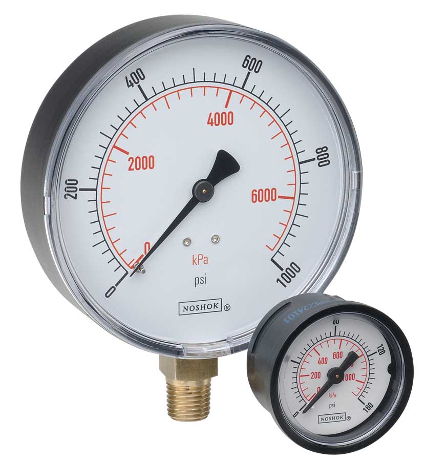 NOSHOK ABS & Steel Dry Pressure Gauges 100 series
 NOSHOK Low Pressure Dry Pressure Gauges-( 200 series)
 NOSHOK PT40 Series High Accuracy Transmitters-Replaces 100,200,615 series
