



Pressure Transmitter Output Signal Guide


A pressure transmitter can have the correct pressure range, wetted materials, and process connection yet still be the wrong device for the job if its output signal does not match the control system. This pressure transmitter output signal guide covers the electrical output formats industrial buyers most often encounter and the specification details that determine whether a transmitter will integrate correctly.
For replacement work, the existing transmitter label and control input card are the starting point. For new installations, select the control architecture first, then confirm the transmitter output, power requirements, wiring method, and communication needs. Signal selection is not just a preference. It affects cable runs, troubleshooting methods, diagnostic capability, intrinsic safety design, and long-term maintainability.
Start With the Receiving Device
The transmitter output must be compatible with the device receiving it: a PLC analog input, DCS input card, chart recorder, local indicator, variable frequency drive, remote terminal unit, or dedicated controller. Confirm whether that input accepts current, voltage, a digital communication protocol, or more than one type.
Do not assume an analog input card is universally compatible. A card configured for a 4-20 mA current loop may not accept a 0-10 V signal. Likewise, an input that supplies loop power has different wiring expectations than a passive input requiring an external power supply. Review the input card documentation for its signal range, input impedance, isolation arrangement, terminal assignment, and required configuration.
A replacement transmitter should also preserve the signal convention used in the existing logic. If a control system interprets 4 mA as zero pressure and 20 mA as full-scale pressure, replacing the transmitter with a reverse-acting or differently scaled unit can create an immediate process-control issue.
4-20 mA: The Standard Industrial Output
The 4-20 mA DC output remains the most common pressure transmitter signal in industrial process applications. It is widely supported, resistant to electrical noise compared with voltage signals, and suitable for long cable runs when loop resistance and supply voltage are correctly calculated.
In a standard linear configuration, 4 mA represents the lower range value and 20 mA represents the upper range value. A transmitter ranged from 0 to 100 psi, for example, outputs 4 mA at 0 psi and 20 mA at 100 psi. At 50 psi, the expected output is 12 mA.
The 4 mA live zero is a practical diagnostic advantage. A reading near 0 mA can indicate an open circuit, failed device, lost power, or broken conductor rather than a valid zero-pressure condition. Many transmitters also drive fault currents below 4 mA or above 20 mA when diagnostics detect an internal or sensor-related error. The exact fault-current behavior should be confirmed against the transmitter specification and the receiving system’s alarm configuration.
Two-Wire Loop-Powered Transmitters
Many 4-20 mA pressure transmitters are two-wire, loop-powered devices. The same pair of conductors provides DC power to the transmitter and carries the analog measurement signal. This arrangement reduces wiring and is common for field instruments installed across a plant or pipeline system.
A two-wire transmitter requires sufficient loop supply voltage after accounting for voltage drop across the input card, wiring, barriers, isolators, displays, and other series devices. Excessive cable resistance can prevent the transmitter from reaching 20 mA, particularly at the high end of its operating range. Long runs, low supply voltage, and intrinsically safe barriers require special attention.
Three-Wire and Four-Wire Designs
Three-wire transmitters typically use separate power and signal conductors with a shared common. Four-wire devices use separate power and output wiring. These configurations are often used when the transmitter has a voltage output, higher power demand, or additional onboard electronics.
Do not wire a three-wire voltage-output transmitter as though it were a two-wire current-loop device. The result can be a no-signal condition or equipment damage. Terminal labels, wiring diagrams, supply voltage limits, and output type should be verified before installation.
Voltage Outputs: Useful but More Application-Dependent
Common voltage output ranges include 0-5 VDC, 1-5 VDC, 0-10 VDC, and 1-10 VDC. These signals are frequently used in OEM equipment, compact machinery, building systems, mobile equipment, and control packages where cable distances are short and the controller is designed for voltage inputs.
Voltage signals can be straightforward to integrate, but they are more sensitive to voltage drop and induced electrical noise than current loops. Cable length, conductor size, shield termination, routing near motors or variable frequency drives, and input impedance all matter. A 0-10 V signal sent over a long, electrically noisy run may be less stable than a 4-20 mA loop in the same application.
The presence or absence of a live zero also changes troubleshooting. With a 0-10 V transmitter, 0 V may represent a valid zero-pressure reading or a failed output, depending on the circuit. A 1-5 V output preserves a live-zero indication similar to 4-20 mA, but it still requires a compatible voltage input and suitable wiring practices.
HART: Analog Measurement With Digital Access
HART-enabled pressure transmitters typically retain a 4-20 mA analog output while superimposing digital communication on the current loop. The analog signal continues to provide the primary process variable to the control system, while a HART communicator, compatible input card, or asset-management system can access configuration and diagnostic data.
For maintenance teams, HART can simplify field verification. Depending on the transmitter model, personnel may check tag information, configured range, sensor status, damping, output trim, and diagnostics without removing the transmitter from service. It can also support remote configuration where site procedures and system design allow it.
HART is not automatically necessary for every pressure measurement point. A basic 4-20 mA transmitter may be the more practical choice for a simple indication or control loop. HART becomes more valuable where documented configuration, predictive maintenance, device diagnostics, or reduced field visits justify the added capability.
When specifying HART, confirm that every device in the loop supports the intended use. Some isolators, barriers, displays, and input cards can interfere with communication if they are not HART compatible. The control system may still read the 4-20 mA process signal normally while digital access is unavailable.
Digital Fieldbus Outputs
Some process installations use digital fieldbus protocols rather than a conventional analog output. These systems can place multiple instruments on a segment and communicate measurement values, diagnostics, and configuration data digitally. The applicable protocol depends on the facility’s installed control platform and engineering standards.
Fieldbus can reduce point-to-point wiring and expand device-level information, but it requires disciplined segment design, compatible host hardware, terminators, power conditioning, addressing, and commissioning procedures. It is generally selected as part of an established plant control strategy rather than chosen solely because a transmitter offers the option.
For an exact replacement, match the existing protocol. A 4-20 mA transmitter is not a direct replacement for a fieldbus transmitter without changes to the control hardware and configuration.
Scaling, Range, and Signal Direction
Output signal range and pressure range are related but separate specifications. A transmitter may be capable of measuring a broad pressure range while being configured for a narrower calibrated span. For example, a sensor rated for 0 to 300 psi may be ranged for 0 to 100 psi to improve usable resolution for the process.
Confirm the lower range value, upper range value, engineering units, and whether the output is linear or reverse acting. Gauge, absolute, compound, differential, and vacuum pressure measurements can all use similar electrical outputs, but the process meaning of the displayed value is different.
A differential pressure transmitter used for flow measurement may also be configured for square-root extraction. In that case, the output is proportional to calculated flow rather than directly linear to differential pressure. Whether square-root extraction belongs in the transmitter or the PLC depends on the plant standard, available diagnostics, and how the loop is maintained.
Installation Factors That Affect Signal Quality
Correct output selection does not compensate for poor installation. Route signal wiring away from high-voltage conductors, motor leads, and switching equipment where practical. Use shielded cable when required by the manufacturer or site standard, and ground the shield according to the control-system design to avoid ground-loop problems.
Verify polarity on DC-powered transmitters. Confirm the enclosure rating, hazardous-area approval, and wiring method are appropriate for the location. If the installation includes a diaphragm seal, capillary system, manifold, or impulse tubing, those components affect pressure response and maintenance access even though they do not change the output signal itself.
After installation, validate the loop at multiple points. A common check is to confirm the transmitter output at zero, 25%, 50%, 75%, and 100% of the configured span, then compare the controller indication to the expected value. This separates a sensor-range issue from a wiring, input-scaling, or display-configuration issue.
Selecting the Correct Output for a New or Replacement Transmitter
For most conventional industrial pressure loops, 4-20 mA is the practical default because it works well with long cable runs, standard PLC and DCS hardware, and common troubleshooting practices. Select HART when digital configuration and diagnostics support the maintenance strategy. Use voltage output where the receiving equipment specifies it and the installation conditions support it. Choose fieldbus only when it matches the existing automation architecture.
Before ordering, document the required output signal alongside pressure type and range, process connection, electrical connection, supply voltage, wetted materials, accuracy, approvals, and temperature limits. NOSHOK transmitter series are available in configurations suited to a range of industrial pressure applications, but the correct series and part number depend on the complete specification, not the output alone.
A transmitter signal should make the measurement usable, verifiable, and maintainable at the control point. Matching it carefully before installation prevents the expensive kind of troubleshooting that starts after a process unit is already waiting on a pressure reading.
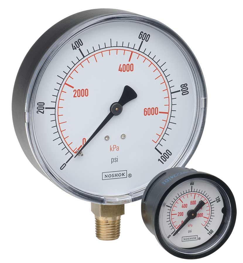 NOSHOK ABS & Steel Dry Pressure Gauges 100 series
 NOSHOK Low Pressure Dry Pressure Gauges-( 200 series)
 NOSHOK PT40 Series High Accuracy Transmitters-Replaces 100,200,615 series