



What Is Gauge Overpressure Protection Used For?

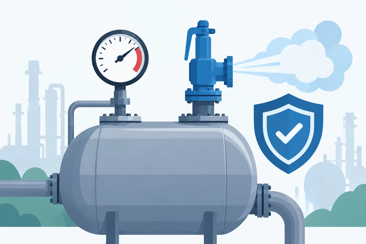
A pressure gauge can appear to be correctly specified until a brief pressure spike bends the sensing element, shifts the pointer, or damages the movement. The question, what is gauge overpressure protection, concerns the methods used to keep those events from shortening gauge life or creating inaccurate pressure readings. It is not one universal component. Depending on the process, protection may come from the gauge construction, a properly selected pressure range, an inline device, or a combination of these measures.
For industrial maintenance teams and OEMs, overpressure protection is a specification issue rather than an accessory decision. The correct approach depends on the normal operating pressure, possible upset pressure, media compatibility, connection type, pressure cycling, and the required indication accuracy after an event.
What Is Gauge Overpressure Protection?
Gauge overpressure protection is the capacity or arrangement that prevents a pressure gauge from being permanently damaged when process pressure rises above its rated range. A gauge may tolerate a limited overpressure for a stated duration, but that does not mean it can withstand any pressure excursion without consequences.
Most mechanical gauges use a Bourdon tube, diaphragm, or capsule to convert pressure into pointer movement. These sensing elements are designed to deflect within a controlled range. When pressure exceeds the design limit, the element can deform permanently. The gauge may still show a reading, but its zero point, span, or repeatability may no longer be dependable.
Protection is therefore intended to do one or more of the following: limit the pressure reaching the instrument, reduce the speed of the pressure change, vent pressure before it reaches a damaging level, or use an instrument designed to tolerate the expected upset condition.
Why Gauge Range Alone Is Not Always Enough
A common selection error is choosing a gauge range that closely matches normal operating pressure. For example, a system running near 100 psi may receive a 0 to 100 psi gauge because the scale appears easy to read. If startup, pump deadhead, thermal expansion, or valve closure can push pressure beyond 100 psi, that gauge has little operating margin.
In many steady-pressure applications, normal pressure is best positioned in the middle portion of the dial rather than continuously near full scale. The exact target depends on the gauge type, required resolution, and manufacturer guidance, but the principle is consistent: a readable scale must also provide margin for expected variation.
Range selection alone has limits. A gauge with a higher range may survive a spike, but it can make normal readings harder to resolve. A 0 to 1,000 psi gauge on a 100 psi process may be protected from an occasional surge, yet it is not an effective choice where operators need to distinguish 95 psi from 105 psi. This is where external overpressure protection or a different measurement strategy becomes necessary.
Common Sources of Overpressure
Overpressure events are often brief enough that they are not visible on a standard analog gauge. The gauge can still experience the event even when the pointer returns to a normal-looking value afterward.
Pump startups and shutdowns, compressor pulsation, rapid valve actuation, water hammer, blocked outlets, pressure regulator failure, and thermal expansion are frequent sources. In hydraulic systems, pressure intensification can occur in localized portions of a circuit. In steam service, improper isolation or startup procedures can expose an instrument to conditions outside its intended range.
Pressure cycling is related but different. Repeated movement across a broad portion of the scale can fatigue a sensing element even when no single event exceeds the gauge’s allowable overpressure. A gauge that fails prematurely may be seeing pulsation, vibration, or cycling rather than one major process upset.
Methods of Gauge Overpressure Protection
The appropriate method depends on whether the hazard is sustained overpressure, a short pressure spike, pulsation, temperature, or a combination of conditions.
Use a Gauge With Suitable Overpressure Capacity
Start with the gauge data sheet. Manufacturers may state maximum working pressure, allowable overpressure, proof pressure, or burst pressure. These terms are not interchangeable. Maximum working pressure addresses continuous service. Allowable overpressure usually identifies a limited condition and duration. Proof and burst values are test-related limits, not necessarily acceptable operating conditions.
A higher-duty gauge construction may be appropriate where pressure excursions are known and controlled within the manufacturer’s stated limits. Do not assume that a liquid-filled case increases pressure capability. Fill fluid can damp pointer movement and help protect the movement from vibration, but it does not change the pressure rating of the sensing element.
Install a Restrictor or Snubber for Pulsation
A restrictor reduces the rate at which pressure changes reach the gauge. Snubbers use an orifice, porous element, or adjustable restriction to damp rapid pulsations. They are commonly used near pumps, compressors, and hydraulic equipment where the process pressure is usable but the pressure signal is unstable.
Restrictors and snubbers work best against frequent, short-duration pulsation. They are not a substitute for relief protection when the system can remain above the gauge’s pressure limit. They can also clog in contaminated media and may create a delayed indication. That delay is acceptable for some local monitoring points and unacceptable for others.
Apply an Overpressure Protector
A gauge overpressure protector is an inline device that isolates the gauge when inlet pressure reaches a preset value. Under normal conditions, process pressure is transmitted to the gauge. Once pressure rises to the set point, the protector closes or otherwise limits communication to the instrument.
This approach is useful when normal operating pressure must be read on a relatively narrow range but occasional excursions are substantially higher. The device set point must be selected with care. If it closes too near normal operating pressure, normal indications may be interrupted. If it closes above the gauge’s allowable limit, it may not protect the gauge soon enough.
Confirm the pressure range, set-point tolerance, wetted materials, process connection, and compatibility with the media. For gauges requiring accurate low-pressure readings, verify whether the device introduces a pressure drop or affects response time.
Use Pressure Relief for Sustained System Upsets
A relief valve, rupture disc, or other system-level protective device controls pressure in the process rather than only at the gauge. This is the correct category of protection when the concern is a sustained overpressure event that could affect piping, vessels, transmitters, valves, and personnel.
A gauge protector should not be treated as a process safety relief device. It protects the instrument connection, not necessarily the system. Where relief is required, sizing, set pressure, discharge routing, and code compliance must be addressed at the system level.
Isolate Difficult Media With a Diaphragm Seal
Diaphragm seals are primarily selected to isolate gauges from corrosive, viscous, sanitary, high-temperature, crystallizing, or plugging media. They can also support a better protection strategy by keeping the gauge away from direct process exposure. However, a diaphragm seal does not automatically provide overpressure protection.
The seal, fill fluid, gauge, capillary arrangement, and process connection must be evaluated as an assembly. Temperature effects, elevation differences, response time, and material compatibility can all influence performance.
How to Specify the Right Protection Method
A practical selection process begins with the actual pressure profile, not just the reported normal pressure. Review normal operating pressure, startup and shutdown conditions, pump or compressor behavior, regulator failure pressure, and the highest credible blocked-in condition. If a data logger is available, transient data may reveal spikes that a dial gauge cannot capture.
Next, compare those conditions with the instrument’s published ratings. Confirm the gauge range, accuracy class, wetted materials, connection size and location, case construction, and allowable overpressure. For liquid, steam, oxygen, corrosive chemicals, or sanitary service, the media and application requirements may dictate additional component choices.
Then select the protection method based on the failure mode. Pulsation points toward a snubber or restrictor. Occasional high excursions with a need for a narrow normal scale may justify an overpressure protector. Sustained upset pressure requires system-level relief. A combination is common, such as a properly ranged gauge with a snubber and a relief device elsewhere in the system.
For replacement work, verify the existing part number rather than matching only the dial range. A replacement may need the same pressure connection, mounting configuration, wetted materials, accuracy, and safety features as the original. Mass Measure supports specification-driven sourcing for NOSHOK gauges and related pressure accessories where exact configuration matters.
Installation and Maintenance Considerations
Even a correctly selected protective device can underperform when installed improperly. Mounting location matters. A gauge located immediately at a reciprocating pump discharge will see far more pulsation than one installed at a properly designed sensing point. Long impulse lines can damp signals, but they may also plug, leak, or introduce lag.
Protectors and snubbers should remain accessible for inspection. If the pointer begins to flutter, fails to return to zero, or produces readings that conflict with another calibrated instrument, investigate the pressure source and the protection arrangement. Replacing the gauge without addressing the cause often repeats the failure.
When a process can exceed the gauge range, treat the gauge as a component of the pressure system, not a standalone dial. A few minutes spent verifying transient pressure, allowable overpressure, and protection-device suitability can prevent recurring replacements and preserve confidence in the reading operators rely on.
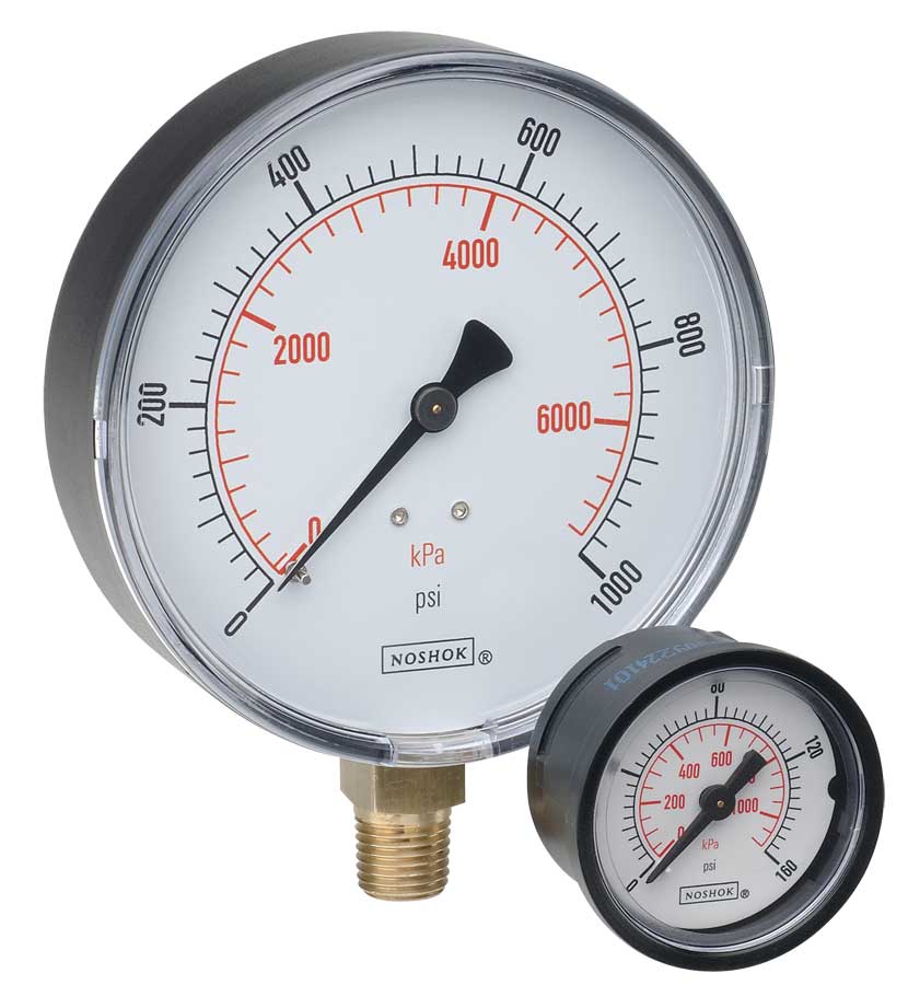 NOSHOK ABS & Steel Dry Pressure Gauges 100 series
 NOSHOK Low Pressure Dry Pressure Gauges-( 200 series)
 NOSHOK PT40 Series High Accuracy Transmitters-Replaces 100,200,615 series
