



How to Prevent Gauge Vibration Damage in Plants


A pressure gauge that appears to be working can still be accumulating mechanical damage on every pump cycle, compressor stroke, or nearby equipment start. To prevent gauge vibration damage, treat vibration as an application condition that affects gauge selection, mounting, connection design, and maintenance intervals – not as a minor installation nuisance.
Needle flutter, a loose pointer, cracked lenses, fatigued bourdon tubes, and drifting readings are common outcomes when a standard dry gauge is installed directly at a vibrating process connection. The correct solution depends on whether the movement comes from equipment vibration, pressure pulsation, acoustic vibration, or a combination of all three.
Identify What Is Moving the Gauge
Before changing the gauge, determine whether the case is vibrating, the pressure signal is fluctuating, or both. These conditions can look similar from a distance, but they require different corrections.
Mechanical vibration transfers through piping, skids, panels, structural steel, or machinery-mounted connections. The entire gauge case may visibly shake, particularly near pumps, compressors, engines, hydraulic power units, and reciprocating equipment. Over time, this vibration can loosen internal components, wear movement pivots, fatigue the process connection, and make the indication difficult to read.
Pressure pulsation originates within the process media. A reciprocating pump, compressor, or rapidly cycling valve can create pressure waves that force the gauge pointer to sweep repeatedly. Even if the gauge case remains still, the internal sensing element and movement are being cycled at a high rate. Pulsation can shorten bourdon tube life and may produce readings that do not represent the average operating pressure.
Many installations experience both conditions. A gauge mounted directly on a compressor discharge line, for example, may be exposed to transmitted machine vibration and rapid pressure pulsation. A liquid-filled gauge alone may improve pointer stability, but it may not adequately protect the sensing element from severe pulsation.
Select a Gauge Built for the Actual Service
Gauge selection starts with the expected pressure range, process connection, wetted materials, accuracy requirement, and environmental exposure. In vibrating service, case construction and fill options are equally relevant.
Liquid-filled pressure gauges are often the first practical choice for moderate vibration and pulsation. Glycerin-filled gauges provide internal dampening, reducing pointer flutter and cushioning movement components. Silicone-filled gauges are generally preferred where lower temperatures or higher temperature variation may make glycerin unsuitable. The fill fluid must remain compatible with ambient conditions and the gauge design.
Liquid fill is not a universal answer. In high-temperature ambient areas, fill expansion can affect case pressure unless the gauge includes appropriate case venting provisions. The vent plug must be handled according to the manufacturer’s instructions. A gauge intended for dry indoor service may also be a better choice where liquid filling offers no meaningful benefit and rapid temperature swings are extreme.
For demanding industrial duty, specify a gauge with a durable case, suitable window material, and a movement designed for the application. Stainless steel cases and wetted components are commonly selected for corrosive environments, outdoor exposure, washdown areas, and applications where process compatibility requires them. The pressure range should also be selected carefully. Running continuously near the top of the dial range leaves less margin for routine pressure spikes and can accelerate fatigue.
When specifying NOSHOK pressure gauges or replacement units, match the existing connection size and location, pressure range, wetted materials, accuracy class, and mounting configuration. A correct-looking gauge with the wrong bottom connection, back connection, or panel-mount arrangement can create unnecessary installation stress or force an unsuitable piping arrangement.
Use Proper Mounting to Prevent Gauge Vibration Damage
Direct mounting is convenient, but it is not always the best installation method. When process piping or equipment transmits significant movement, remote mounting is often the most effective way to protect the instrument.
A gauge can be moved to a rigid panel, bracket, or instrument stand and connected with appropriately rated tubing or a flexible connection arrangement. The mounting point should be structurally stable and positioned where operators can read the dial without placing themselves near hot surfaces, rotating equipment, or hazardous process areas. Support the tubing so its weight and vibration do not load the gauge connection.
Avoid using the gauge itself as a support point for pipe alignment. Misaligned threaded connections, unsupported tubing, or rigid piping that is forced into place can place bending stress on the socket. Vibration then turns that initial stress into a fatigue failure risk.
A panel-mounted gauge can be a good option for OEM equipment, control enclosures, and packaged systems, provided the panel is not vibrating excessively. If the enclosure is mounted directly to a machine frame, consider isolation at the enclosure or instrument mounting location rather than assuming the panel will eliminate vibration.
Thread sealant should be applied carefully and kept clear of the pressure passage. Excess sealant can obstruct small passages, interfere with dampening devices, or enter the process line. Tighten the gauge using the wrench flats on the socket, not the case.
Control Pulsation at the Process Connection
When the pointer is oscillating due to pressure pulsation, address the pressure signal before it reaches the gauge. A pressure snubber, restrictor, or pulsation dampener can reduce the amplitude and frequency of pressure fluctuations seen by the instrument.
A snubber or restrictor adds a controlled flow restriction between the process and the gauge. This can stabilize the pointer and reduce cycling of the bourdon tube. Selection depends on media cleanliness, viscosity, operating pressure, and the required response time. A restriction that is too small may plug in contaminated service or make the gauge respond too slowly to useful process changes. One that is too large may provide little protection.
For severe reciprocating pump or compressor service, a properly sized pulsation dampener may be necessary upstream of the gauge connection. This approach reduces pulsation energy in the system rather than relying only on a small instrument accessory. It is often the better choice when multiple instruments, transmitters, switches, or valves are exposed to the same unstable pressure signal.
Do not install a small-orifice restrictor in service where solids, sludge, crystallization, or viscous media will predictably foul it. In those applications, a diaphragm seal, flush connection, remote seal system, or alternate measurement location may be more appropriate. The goal is stable measurement without creating a maintenance point that blocks the instrument from the process.
Protect the Gauge From Temperature and Process Effects
Vibration problems are frequently compounded by heat, corrosion, or incompatible media. A gauge installed on a hot line may require a siphon, cooling element, capillary arrangement, or remote mounting to keep the instrument within its allowable temperature limits. Excessive temperature can damage internal components and change the behavior of liquid fill.
For corrosive, sanitary, high-viscosity, or solids-bearing media, a diaphragm seal can isolate the gauge from the process while preserving pressure transmission through a compatible fill system. Seal selection must account for diaphragm material, process connection, fill fluid, temperature, and pressure range. A diaphragm seal is not simply an accessory added after a gauge failure. It is part of the measurement assembly and should be specified as such.
Also verify that the gauge is not being exposed to overpressure. Short spikes can be more damaging than a stable operating condition near the normal range. If spikes are expected, consider an overpressure protector, a higher-range gauge where resolution remains acceptable, or a system-level change that reduces the transient.
Inspect Gauges Before They Fail
A vibration-exposed gauge should be part of a defined inspection routine. Look for pointer flutter, zero shift after isolation and depressurization, fogging, liquid loss, damaged cases, loose mounting hardware, leaking connections, and unreadable dials. A gauge that has lost its fill fluid or shows a bent pointer should not remain in critical service simply because it still indicates pressure.
Compare readings against a calibrated reference when process conditions permit. If a gauge repeatedly shifts out of tolerance, replacing it with the same model without correcting the installation usually repeats the failure cycle. Document the location, equipment operating state, failure appearance, and time in service. That information helps distinguish a product selection issue from a piping, pulsation, or mounting issue.
For critical control points, consider whether a mechanical gauge is serving as a local visual indicator, a verification device, or a primary operating reference. The required accuracy, response time, and inspection frequency should match that role. A local gauge on a utility line may tolerate more dampening than a gauge used to monitor a rapidly changing process condition.
The most reliable installation is usually not the one with the most accessories. It is the one where the gauge, connection method, dampening approach, and process conditions have been matched before the instrument is placed in service.
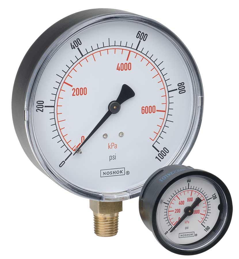 NOSHOK ABS & Steel Dry Pressure Gauges 100 series
 NOSHOK Low Pressure Dry Pressure Gauges-( 200 series)
 NOSHOK PT40 Series High Accuracy Transmitters-Replaces 100,200,615 series