



Pressure Manifold Versus Needle Valve Selection

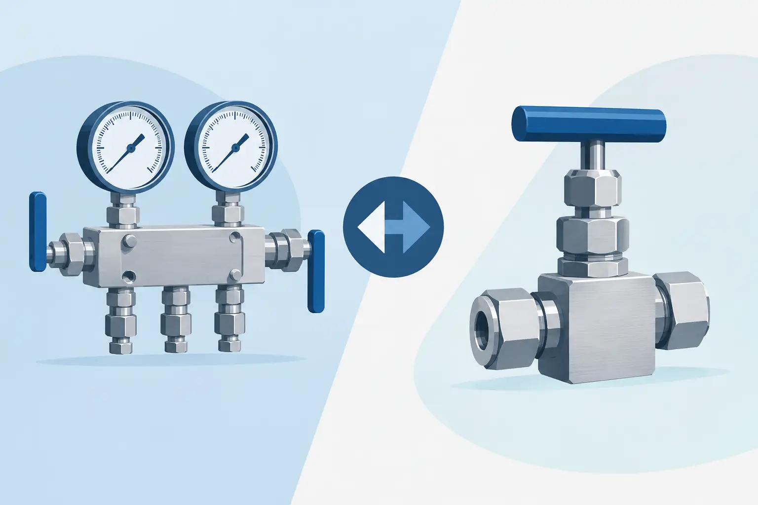
A pressure manifold versus needle valve decision is usually made at the instrument connection, but it affects far more than installation convenience. The selected valve arrangement determines how safely a gauge, pressure transmitter, or differential pressure transmitter can be isolated, vented, equalized, calibrated, and replaced. For industrial buyers, the correct choice depends on instrument type, process pressure, connection standards, material compatibility, required operating procedures, and the number of functions needed at the point of measurement.
A needle valve is often the right answer for a straightforward single-pressure isolation point. A manifold is generally the better fit when the installation requires multiple controlled functions in one compact assembly. Neither component is automatically superior. The specification has to match the measurement loop.
Pressure Manifold Versus Needle Valve: Core Difference
A needle valve is a single-valve device with a tapered stem that provides controlled flow restriction and positive shutoff. In instrumentation service, it is commonly installed between the process connection and a pressure gauge, transmitter, pressure switch, or other sensing device. Its primary role is isolation. Depending on the installation, it may also be used to reduce pulsation effects, control the rate of pressure application, or provide a controlled bleed path.
A pressure manifold combines multiple valve functions into a machined block or assembled valve body. Common configurations include 2-valve, 3-valve, and 5-valve manifolds. These assemblies are designed specifically for instrument mounting and calibration access, particularly on pressure and differential pressure transmitters.
The distinction is functional. A needle valve controls one path. A manifold organizes several paths and functions at the instrument interface. A manifold may include block valves for process isolation, an equalizing valve to balance pressure across a differential transmitter, and vent or bleed valves for depressurization and test work.
When a Needle Valve Is the Better Choice
A needle valve is appropriate when the installation has one process pressure source and one instrument that only needs isolation. A local pressure gauge on a hydraulic skid, compressed-air receiver, pump discharge line, or general process line is a typical example. The valve allows the instrument to be removed or serviced without shutting down the entire process section, provided the system design permits local isolation.
Needle valves are also useful where controlled pressure application matters. Opening a valve gradually can help prevent a sudden pressure shock to a sensitive gauge or transmitter. This does not replace proper overpressure protection or pulsation control, but it gives the technician a controlled means of bringing the instrument online.
For these installations, selection should focus on the pressure rating, body and wetted material, end connections, stem design, packing material, temperature limits, and compatibility with the process media. A stainless steel needle valve may be suitable for many corrosive or outdoor service conditions, while brass may be acceptable for compatible lower-risk pneumatic or hydraulic applications. Material selection must be based on the actual media, pressure, temperature, and environmental exposure.
A single needle valve can be less expensive and easier to replace than a manifold. It also simplifies the bill of materials when no equalization, venting, or calibration connection is required. The trade-off is that a basic needle valve does not provide the coordinated isolation and testing functions needed for more complex transmitter installations.
When a Pressure Manifold Is Required
A pressure manifold is normally specified when the instrument requires more than one controlled valve function. Differential pressure transmitters are the clearest example. These instruments measure the difference between a high-pressure side and a low-pressure side. Both sides must be isolated during maintenance, and they often must be equalized before removal or calibration.
A 3-valve manifold commonly provides two block valves and one equalizing valve. The block valves isolate the high and low process connections. The equalizing valve connects the two sides of the transmitter so pressure can be balanced across the sensing element. This supports safer shutdown and helps avoid applying an excessive differential pressure during startup or maintenance.
A 5-valve manifold adds vent or test valves to the block-and-equalize arrangement. These additional ports provide a controlled means to vent trapped pressure, connect calibration equipment, or perform test procedures. In installations where technicians regularly verify transmitter performance, the added functionality can reduce service time and limit the number of temporary fittings required.
For direct-mount transmitter applications, a manifold can also reduce the number of individual fittings, nipples, and threaded joints. Fewer connection points may simplify assembly and reduce potential leak paths. That benefit depends on using the correct manifold style, connection configuration, thread form, sealing method, and torque procedure.
Instrument Type Drives the Selection
The fastest way to narrow the choice is to identify the instrument and its measurement principle.
A pressure gauge, pressure switch, or single-pressure transmitter typically measures pressure from one process connection. If the application only requires local isolation, a needle valve is often sufficient. A valve with an integrated bleed port may be appropriate where trapped pressure must be relieved before gauge replacement or transmitter removal.
A differential pressure transmitter requires separate high- and low-pressure connections. In most cases, an instrumentation manifold is the appropriate arrangement because the transmitter needs controlled isolation and equalization. Using separate needle valves can be done in certain engineered assemblies, but it introduces more components and can make correct operating sequence dependent on field practice. A purpose-designed manifold places the required functions in a defined configuration.
Remote-mounted instruments may use tubing, fittings, and individual isolation valves rather than a direct-mount manifold. This is common where temperature, vibration, access limitations, or process conditions require the transmitter to be located away from the tap point. The selection still follows the same principle: use a manifold where multiple instrument functions must be managed together, and use individual needle valves where each line requires independent, single-path control.
Connection and Mounting Details Cannot Be Assumed
A valve or manifold that has the right function but the wrong connection is not a valid replacement. Buyers should verify process connection size, thread type, instrument connection, flange pattern where applicable, port orientation, and mounting style before ordering.
Thread standards deserve particular attention. NPT connections are common in North American industrial systems, but other thread forms and mounting patterns are also used. Male and female orientations must match the existing assembly. For transmitter manifolds, verify whether the component is intended for direct mounting, remote mounting, coplanar mounting, or a specific transmitter interface.
Port spacing and orientation affect installation clearance. A compact manifold may simplify a crowded panel or transmitter rack, while the wrong valve handle orientation can create an access problem for maintenance personnel. If a replacement is being selected from an existing tag, drawing, or bill of materials, confirm the full manufacturer part number rather than relying only on a general product description.
Pressure Rating, Materials, and Process Compatibility
The maximum working pressure of the valve assembly must meet or exceed the system requirement at the applicable temperature. Do not select solely by the normal operating pressure. Consider pressure excursions, hydrostatic testing requirements, startup conditions, and any pressure spikes generated by pumps, compressors, or fast-acting valves.
Material compatibility is equally critical. The body, stem, packing, seals, and wetted components must tolerate the media. Water, steam, air, hydrocarbons, chemicals, oxygen service, and sanitary process fluids can impose very different requirements. Stainless steel is widely specified for industrial instrumentation because of its corrosion resistance, but it is not a universal solution for every chemical or chloride environment.
For oxygen or other specialty service, cleanliness and manufacturer-approved configuration may be as important as the base material. For high-temperature service, verify packing and seal limits. For outdoor service, account for corrosion exposure, freezing risk, UV exposure where applicable, and valve accessibility under operating conditions.
Maintenance and Calibration Considerations
The right valve arrangement should make maintenance safer, not merely make initial installation easier. Before selecting a needle valve or manifold, consider how the instrument will be isolated, depressurized, tested, and returned to service.
A gauge mounted behind a plain isolation valve may still retain process pressure between the valve and gauge. If technicians must remove that gauge, a bleed feature or separate vent path may be needed. Similarly, a differential pressure transmitter requires a documented valve sequence to avoid damage or inaccurate readings. A 3-valve or 5-valve manifold supports that sequence by placing block, equalizing, and venting functions at the transmitter.
Calibration requirements also influence the specification. If a transmitter is routinely tested in place, vent or test ports can reduce setup time and improve repeatability. If maintenance is infrequent and the process can be shut down safely, a simpler arrangement may be justified. The decision should reflect the plant’s procedures, not only the purchase price of the component.
A Practical Selection Method
Start with the measurement task. For a single-pressure instrument requiring isolation, specify a needle valve with the required pressure rating, material, connection type, and any necessary bleed capability. For a differential pressure transmitter, begin with a 3-valve or 5-valve manifold and select the configuration based on whether venting and calibration access are required.
Then verify the complete installation: process media, operating and maximum pressure, temperature, mounting arrangement, instrument interface, port orientation, required certifications, and maintenance procedure. This approach avoids a common replacement error: selecting a component that physically threads into the system but does not provide the required operating function.
Mass Measure supports specification-driven sourcing for NOSHOK instrumentation components, where exact valve configuration, material, connection, and application details matter. When an existing part number is available, use it as the starting point and confirm all critical parameters before placing a replacement order.
The most useful final check is simple: picture the technician isolating the instrument, relieving trapped pressure, connecting test equipment, and restoring the loop to service. If each step can be completed safely with the selected arrangement, the valve choice is aligned with the application.
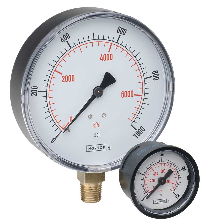 NOSHOK ABS & Steel Dry Pressure Gauges 100 series
 NOSHOK Low Pressure Dry Pressure Gauges-( 200 series)
 NOSHOK PT40 Series High Accuracy Transmitters-Replaces 100,200,615 series
